
Technical data
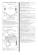
15. Pressure Relief Valve. See fig. 37 and 39.
Check that the electricity supply to the appliance is turned off.
Drain the central heating circuit as described in Section 14.2 (a).
Hinge the facia panel down into the Servicing Position as
described in Section 13.3 (c).
Remove the bottom panel as described in Section 13.3 (d).
Carefully ease the copper capillary tube to one side to clear the
retaining clip. Pull out the retaining clip, undo the discharge pipe
connection and remove the valve from the plastic manifold.
Retain the clip, discard the valve
Fit the replacement valve in reverse order. Reconnect the
discharge pipe.
Reassemble the appliance in the reverse order.
Open the valves and fill and re-pressurise the system as
described in Section 11.
16. Filling Loop. See figs. 37 and 39.
Check that the electricity supply to the appliance is turned off.
Drain the central heating circuit as described in Section 14.3 (a).
Hinge the facia panel down into the Servicing Position as
described in Section 13.3 (c).
Drain the central heating circuit as described in Section 14.3 (a).
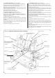
Remove the screw securing the filling loop to the underside of
the water diverting valve.
Remove the clip retaining the filling loop to the plastic flow manifold.
Remove the wire clip joining the two sections of the filling loop
and slide the air gap section in the direction of the arrow.
Remove from the appliance.
Fit the replacement assembly in the reverse order.
Replace the ‘O’ ring seals.
Open the valves and fill and re-pressurise the system as
described in Section 11.1.
Reassemble the appliance in the reverse order.
17. Water to Water Heat Exchanger. See figs. 37 and 39.
Check that the electricity supply to the appliance is turned off.
Drain the central heating and domestic hot water circuits as
described in Sections 14.2 (a) and (b).
Hinge down the facia panel into the Servicing Position as
described in Section 13.3 (c).
Remove the bottom panel as described in Section 13.3 (d).
Remove the filling loop as described in Section 14.3 (16).
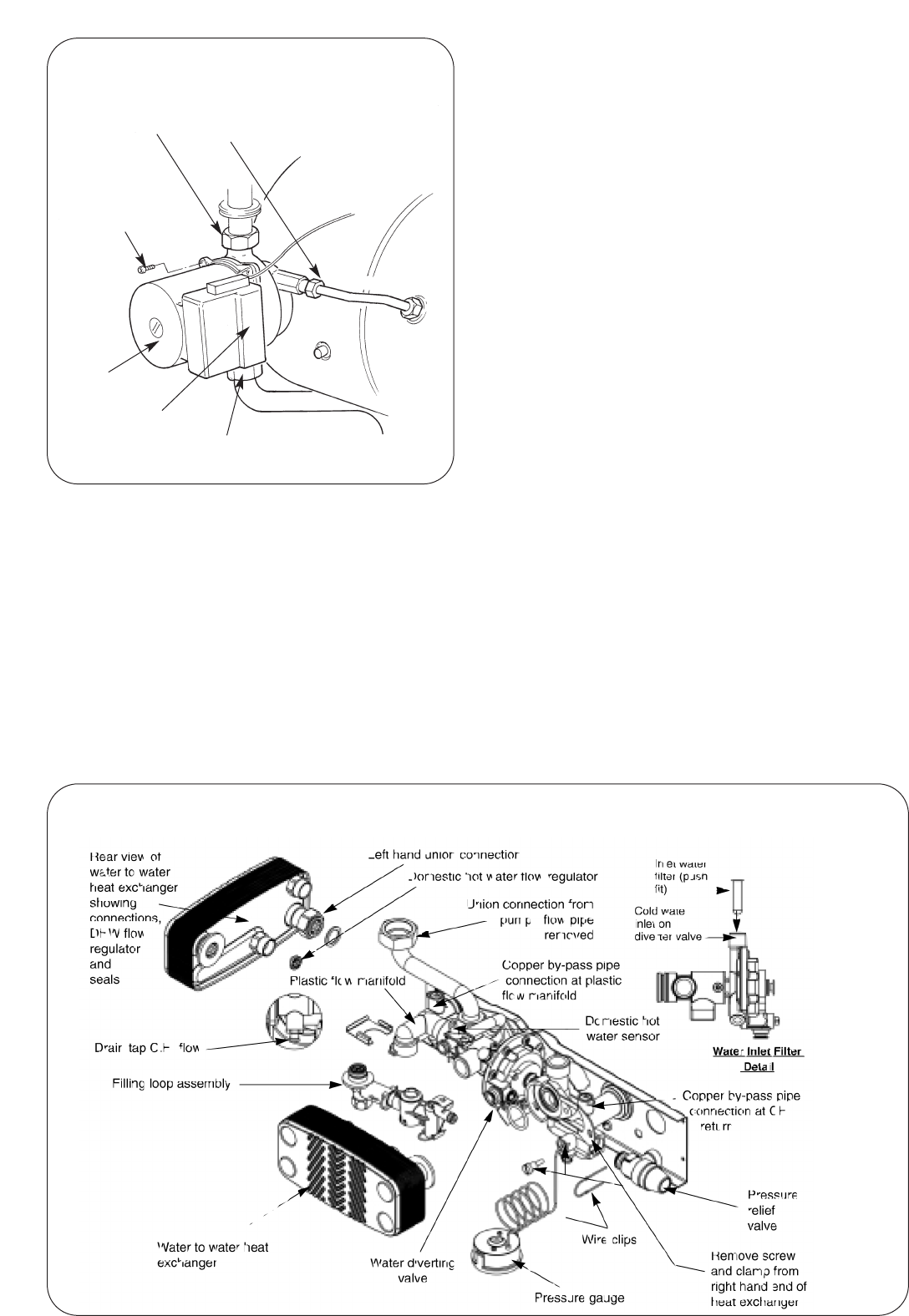
Unscrew the left hand union connection to the diverter valve.
Remove the screw and clamp from the right hand end of the
heat exchanger.
Pull the heat exchanger forwards about 10mm to release from
the other two connections and remove from the appliance.
The plastic hot water flow regulator is located in the cold water
inlet accessible from the rear of the heat exchanger. Remove the
flow regulator (push fit) and retain.
Discard the heat exchanger retain the screw and clamp.
Fit the replacement heat exchanger in the reverse order.
Fit a new fibre sealing washer and ‘O’ ring seals. Lubricate the
‘O’ rings seals with silicone based grease.
Reassemble the appliance in the reverse order.
Open the valves and fill and re-pressurise the system as
described in Section 11.
29
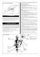
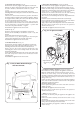
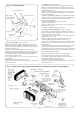
Fig. 38. Circulating pump
Expansion vessel
Unscrew union fittings
Allen screws (4)
remove if changing
pump head only
Pump head
Pump
Electrical
connection
cover
Unscrew union
fitting
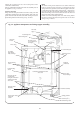
Fig. 39 Filling Loop, Water to Water Heat Exchanger and Domestic Hot Water Flow Regulator