
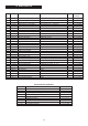
Technical data
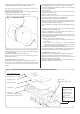


25. Secondary Heat Exchanger. See figs. 32, 33, 34, 35, 36, 37,
39, and 43.
Check that the electricity supply to the appliance is turned off.
Drain the central heating circuit as described in Section 14.2 (a).
The secondary high efficient heat exchanger is housed in a
stainless steel box. The assembly is located inside and at the rear
of the inner casing.
To access the assembly:
i) Remove the inner casing cover, fan, flue hood assembly and
disconnect the overheat thermostat as described in
Section 13.3 (b), (e), (f) and Section 14.3 (4).
ii) Remove the combustion chamber front and sides assembly
and unhook the securing rods out of the locations in the inner
casing as described in Section 13.3 (g).
iii) Remove the gas to water heat exchanger, rear fibre insulation
pad and burner assembly as described in Section 14.3 (5), (6)
and (7).
iv) Unscrew the three screws either side of the inner casing
securing the rear of the combustion chamber to the inner casing
and remove.
v) Slacken the screw in the clip securing the flue bend to the top
of the heat exchanger. Ease the bend out of the appliance.
vi) Remove gas valve section 14.3 (c).
vi) Remove the screw located on top of the inner casing.
Retain all components removed from the appliance.
To remove the assembly:
i) Remove the top screw securing the heat exchanger to the inner
casing. Retain the screw.
ii) Pull off the two clips securing the flow and return pipes to the
heat exchanger located under the inner casing. Ease the ‘O’ ring
connections just clear of the fittings.
Warning: A quantity of primary water will remain in the heat
exchanger and pipework.
iii) Unscrew the two union lock nuts securing the flow and return
connections to the inner casing.
iv) Disconnect the plastic drain pipe to the condensate trap.
v) Ease the assembly out of the locations in the base of the inner
casing and clear of the appliance.
If a blockage is suspected the stainless steel box may be flushed
out with clean water and reassembled.
Alternatively discard the assembly and sealing gasket and
replace with a new assembly.
32
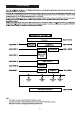
Fig. 43. Secondary Heat Exchanger
Remove screw securing bracket to
flue bend
Remove top screw securing heat
exchanger to inner casing
Slacken the screw in the clip
securing the flue bend to the
top of the heat exchanger.
Ease the bend clear of inner
casing.
Remove the sealing gasket.
Disconnect the plastic drain pipe
to the condensate trap.
NB: A quantity of primary water
will remain in the heat exchanger
Pull off the clips from the flow and
return connections. Ease the 'O'
ring connections just clear of the
fitting.
Unscrew the locknuts securing
the flow and return connection.
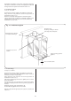
Rear of combustion
chamber
To access the secondary
heat exchanger remove the
three screws either side of
the inner casing and remove
the rear of the combustion
chamber.
Secondary
heat exchanger
Inner casing
Fan outlet spigot
Remove the
top screw