24CDi, 28CDi & 35CDi II COMBI APPLIANCE 24CDi Fanned Flued (RSF) 24CDi Balanced Flued (BF) 24CDi Open Flued (OF) 28CDi Fanned Flue (RSF) 35CDi II Fanned Flue (RSF) G.C. NUMBERS NATURAL GAS L.P.G.
EXCELLENCE COMES AS STANDARD Thank you for purchasing a Worcester CDi gas-fired combination appliance. Worcester CDi appliances are made by Worcester Heat Systems and the strictest quality control standards are demanded throughout every stage of production. Indeed, Worcester Heat Systems have led the field in innovative appliance design and performance for more than 30 years.
GENERAL INFORMATION GAS SAFETY (INSTALLATION AND USE) REGULATIONS 1998 It is the law that all gas appliances must be installed by a competent person in accordance with the above regulations. Failure to install appliances correctly could lead to prosecution. It is in your interest and that of safety to ensure compliance with the law. The manufacturers notes must not be taken, in any way, as overriding statutory obligations. WARNING: This appliance must be earthed and protected by a 3 amp fuse.
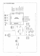
When hot water is no longer required the appliance pump (or fan) may continue to operate to dissipate the residual heat within the boiler. A flow restrictor is fitted within the appliance which limits a hot water delivery rate to a maximum of: 24CDi 28CDi 35CDi II 9.0 (±15%) litres/minute 10.0 (±15%) litres/minute 12.0 (±15%) litres/minute Hot Water and Central Heating mode: Fig. 1. System Diagram.
GENERAL NOTES CENTRAL HEATING SYSTEM During the first few hours of operation of the central heating system, check that all radiators are being heated at an even rate. Should the upper area of a radiator be at a lower temperature than the base of the radiator, it should be vented by releasing air through the venting screw at the top of each radiator. Make sure your installer shows you how to carry out the operation.
CLEARANCES 24,28CDi RSF 35CDi II 24CDi OF 24CDiBF Left-hand side Right-hand side In Front Above 10 10 600 180 10 10 600 180 10 10 600 300 10 10 600 100 Below 200 200 200 200 Minimum clearances in millimetres. Your installer will have provided adequate space around the appliance for safety and servicing. Do not restrict this space by the addition of cupboards, shelves etc. close to the appliance. ROOM THERMOSTAT A room thermostat may be fitted for control of the central heating temperature.
The water hardness may be determined using the standard test paper or by reference to the local Water Company. Further information may be obtained from Worcester Heat Systems Technical Helpline. AIR SUPPLY FOR OPEN FLUED (O.F.) APPLIANCES Your installer will have made arrangements for an adequate supply of fresh air to the appliance. Fresh air is required for combustion. Do not block up any air ways which may be let into a wall or door.
OPERATION OF CONTROLS OPERATING SWITCH In the ‘ ’ position there is no mains electricity to the appliance. In the ‘I’ position mains electricity is connected to the appliance. CENTRAL HEATING TEMPERATURE CONTROL The position of this knob will determine the temperature of the water delivered to the radiators between the ‘I’ and ‘MAX’ position.
INDICATOR LIGHTS Mains electricity indicator: OFF : No mains electricity to the appliance ON : Mains electricity is connected to the appliance Central heating demand indicator: OFF : No demand for heat to the central heating circuit ON : Central heating demand FLASHING SLOW : Ignition lockout (once per second) FLASHING FAST : Appliance fault (other than ignition (five times per second) lockout) Domestic hot water demand indicator: OFF : No demand for domestic hot water ON : Domestic hot water demand FLASHIN
TO LIGHT AND STOP THE APPLIANCE TO LIGHT THE APPLIANCE Check that the water valves to the central heating circuit are open. On sealed systems check that the grey needle on the pressure gauge is not below the required pressure. Switch on the mains electricity. The green power on indicator will light. Set the room thermostat, if fitted, to maximum. Turn the central heating temperature control knob to ‘MAX’. The red central heating demand indicator will light.