24Si II / 28Si II WALL MOUNTED COMBINATION BOILERS FOR CENTRAL HEATING AND MAINS FED DOMESTIC HOT WATER INSTALLATION AND SERVICING INSTRUCTIONS Worcester supports the Benchmark code of practice This appliance is for use with Natural Gas or LPG (Cat II 2H3P TYPE C12 & C32) 24Si II GC NUMBER 47 311 65 (N.G.) GC NUMBER 47 311 66 (L.P.G.) 28Si II GC NUMBER 47 311 67 (N.G.) GC NUMBER 47 311 68 (L.P.G.) GB/IE APPLIANCE OUTPUTS Domestic Hot Water Minimum Maximum 24Si II 28Si II 6.9 kW 8.
Contents 1. Installation Regulations . . . . . . . . . . . . . . . . . . . . . . . . . . . Page 2 2. Introduction . . . . . . . . . . . . . . . . . . . . . . . . . . . . . . . . . . . . . Page 2 3. Technical Data . . . . . . . . . . . . . . . . . . . . . . . . . . . . . . . . . . . Page 4 4. Siting the Appliance . . . . . . . . . . . . . . . . . . . . . . . . . . . . . . Page 7 5. Flue Terminal Positions . . . . . . . . . . . . . . . . . . . . . . . . . . . . Page 7 6. Air Supply . . . . . . . . . . . . . .
the compartment provided the increased clearances are used. See Fig. 5. The spaces specified for servicing must be maintained.(See Table 8). There is space for the service pipes to pass at the back of the appliance. 2.10 Safety The appliance must not be operated with the inner casing cover removed or without being full of water and pressurised. The gas and electricity supplies must be turned off before working on the appliance. Temperature monitoring controls are fitted to prevent overheating.
3. Technical Data Table 1. 24Si II Table 1. NOMINAL BOILER RATINGS (10 Minutes After Lighting) BOILER ADJUSTED FOR G20 (Natural Gas) BURNER OUTPUT INPUT (Net) GAS RATE PRESSURE kW kW m bar. m3/h 6.9 7.9 0.9 0.84 24 26.4 12.1 2.8 6.9 24 28Si II NOMINAL BOILER RATINGS (10 Minutes After Lighting) BOILER ADJUSTED FOR G20 (Natural Gas) BURNER OUTPUT INPUT (Net) GAS RATE PRESSURE kW kW m bar. m3/h 8.1 9.2 0.7 0.97 28 30.7 13.1 3.25 BOILER ADJUSTED FOR G31 (Propane) 7.9 3.1 0.32 26.4 35.0 1.08 8.
Table 5 PERFORMANCE SPECIFICATIONS PRIMARY WATER CAPACITY 24Si II 28Si II litres 2.0 IP RATING (WHOLE OF BOILER) IP 20 MAXIMUM MAINS INLET PRESSURE bar MINIMUM MAINS INLET PRESSURE (WORKING) FOR MAXIMUM FLOW bar 1.0 MINIMUM MAINS INLET PRESSURE (WORKING) FOR OPERATION bar 0.25 DOMESTIC HOT WATER TEMPERATURE RANGE °C 40 - 60 MAXIMUM CENTRAL HEATING FLOW TEMPERATURE °C 82 (nom) MAXIMUM CENTRAL HEATING SYSTEM SET PRESSURE bar 2.65 MINIMUM CENTRAL HEATING SYSTEM PRESSURE bar 0.
Fig. 6. Side flue opening Fig. 3. Appliance casing dimensions and required clearances for installation/servicing 30 150 114 230 24Si II = 400 28Si II = 440 10 10 200 All dimensions in mm All dimensions in mm Fig. 4. Appliance casing dimensions and required clearances (side view). Fig. 7. Pipework connections Valves shown closed. 114 230 F 600 A 740 B C D E View of underside of appliance showing connections 360 200 All dimensions in mm 20 Fig. 5.
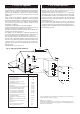
4. Siting The Appliance 5. Flue terminal positions The appliance may be installed in any room but refer to the requirements of the current IEE Regulations and, in Scotland, the relevant electrical provisions of the Building Regulations with respect to the installation of appliances in rooms containing baths or showers. In Eire refer to the ETCI rules for electrical installations.
6. Air Supply 7. Sealed System 6.1 A separate vent for combustion air is not required. Refer to BS5440:2. If the appliance is in a cupboard or compartment then, because of the low casing losses, it is not necessary to have any cooling ventilation for the boiler. Refer to Section 2.5. There must be increased clearance around the appliance to allow the free movement of the air. Refer to Table 8 and Fig 3, 4 and 5.
Fig 10 - System Fill Fig 11 - System make up 4 2 Mains water supply Heating return Hose union 1 300mm Above the highest point of the system 3 Non return Non return valve valve 5 6 1.Central Heating Return 2.Auto Air vent 3.Non-return Valve 4.Make-up Vessel 5.Stop Cock 6.Fill Point Stop cock Temporary hose Test cock 8. Domestic Hot Water 9. Gas Supply It may be necessary to contact the local Water Company before connecting the appliance.
Fig. 12. Wiring diagram.
LIVE IN ST2 Pin N ST2 Pin L On/Off switch 11 ST15 right pin ST2 (LS) red Electronics Electronics N Convert AC to low voltage electronics low high ST1 right pin ST2 (LR) Spark Indicators Settings Electronics/ microprocessor (Safety Low Voltage) white ST1 centre pin Optional link Room thermostat ST2 (NS) Transformer Fuse F2 (1.
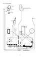
Fig. 14. Access to internal fuses and electrical connections. Fig. 15 . Mains electricity connections. 1 3 2 N Ns Ls Ns L 230V Ls MAINS LR 230V 4 1. Connection cover fixing screws 2. Connection cover 3. Control panel 4. Connections 11.6 Gas and Water Pipes Remove the gas cock and fix the appropriate fitting to connect the inlet pipe and refit. Refer Fig 17. If it is necessary for any of the pipes to run up the back of the appliance then they must be arranged to pass behind the expansion vessel.
Fig. 19 . Wall mounting frame Fig. 17 . Manifold assembly 3 Wall Frame Wall Frame Fibre Washer 65 CH Flow 65 65 2 4 1 65 1. Wall mounting frame 2. Hanging bracket 3. Appliance 4. Support hook DHW Flow Gas DHW Cold Inlet CH Return Lift the appliance to the wall, engage in the top support and lower onto the manifold assembly. Tighten the gas and water connections. Fit a discharge pipe to the relief valve leading it away from any electrics or where it might be a hazard.
Fig. 21. Inner case and facia fixing Fig. 22. Flue spigot and restrictor 1 3 2 3 1 1. 2. 3. 4. Flue spigot fixing screws Flue spigot Restrictor ring Flue spigot fixing holes 4 Fig.23. Standard flue assembly 4 Terminal assembly L 5 Flue turret assembly 10 9 7 2 Fixing screw 8 6 2 Telescopic adjustment Appliance casing 7 11 Fit the flue restrictor ring by unscrewing the flue spigot from the boiler. Refer to Fig. 22.
Fig. 24. Extension duct Terminal assembly L Flue turret assembly Fixing screw Appliance Fixing screw casing Ducts of equal length Fig. 25. Flue duct length - side Terminal assembly L Flue turret assembly It will be necessary to cut the ducts Fig. 26.
Prepare the flue assembly as described in Section 11.8. Fig. 27 . Flue Turret Fixing Fit the rubber sealing gasket centrally onto the terminal assembly and tighten the clamp. Refer to Fig. 28. Apply the plastic tape to the air duct to be in contact with the external brickwork. 1 From inside push the assembly through the wall so that the gasket flange is against the outer face. Refer to Fig. 28. It may be necessary to adjust the legs of the flue centering ring.
If Z is greater than 725mm then two extension duct assemblies will be required, the first assembly being cut to length as plain tubes. Connect the mains supply lead to the appliance and secure in the cable clamp. Make sure that the lead is isolated before connection. Refer to Section 10. Check that there is sufficient loose lead to allow the release of the facia panel assembly and that the earth lead of the mains supply is longer than the live and neutral leads. Fit the facia-mounted clock or programmer.
Fig 36 - Mains Voltage External Controls Connections Fig. 34. Programmer cover 3 N Ns Ls Ns Ls LR spare L N Ns Ls Ns Ls LR spare L Remove Link Live Switched Live ST2 Neutral Live Neutral 1 Switched Live ST2 Remove Link Motor 230 V Room Thermostat Connections 2 230 V Programmer Connections 230 V room thermostat and Programmer Connections 1. Programmer connections 2. Boiler outer casing 3.
Fig. 38. Pump venting. 12. Commissioning The Appliance Water Treatment: For optimum performance after installation, this boiler and its associated central heating system should be flushed in accordance with the guidelines given in BS7593: 1992 – Treatment of water in domestic hot water heating systems. Full instructions are supplied with proprietary cleansers sold for this purpose. If an inhibitor is to be used after flushing, it should be used in accordance with the manufacturers instructions.
Unscrew and remove the control connector cover to display the mode switch. Refer to Fig 32. Check that all the radiator valves are open. Check that the system is fully vented, pressurised and set to the required pressure as indicated on the gauge. Set the temperature control knobs to maximum and the clock/programmer to operate continuously. Fully open a hot tap. 12.7 Central Heating Check that all the radiator valves are open.
13. Handover Fig. 42. Inner case and facia fixing 3 1 Fig. 41. Facia controls 7 6 5 12 1 1. 2. 3. 4. 2 Mains On/Off control CH temperature control DHW temperature control System pressure gauge 3 4 4 5. Optional programmer 6. Lockout indicator lamp and reset button 7. Burner indicator lamp 5 7 2 6 Hand over the User Booklet and the completed Benchmark Checklist. Explain how to operate the appliance safely and efficiently.
13 Fig. 44. Inner case components 12 11 1 10 15 2 14 9 3 8 4 7 5 6 1. Flue hood 9. Inner case 2. Primary sensor 10. Fan assembly 3. Heat exchanger 11. Inner case cover fixing (top) 4. Combustion chamber assembly 12. Air pressure switch 5. Spark electrode assembly 6. Inner case cover fixing (bottom) 13. Combustion sensing point 7. Burner assembly 15. Main wiring harness 14. Fan harness 8.
Inner Case Cover Unscrew the four screws and remove. Refer to Fig 42. Combustion Chamber Unscrew the two screws at the top and the two wing nut extended screws at the sides, pull forward and remove. Refer to Fig 44. Fan Carefully pull off the electrical connections and the tubes from the airflow-sensing device. Unscrew the four screws and remove the fan assembly. Refer to Fig 45. Flue Hood Remove the fan. Unscrew the four screws and slide out the hood. Refer to Fig 47. Burner Remove the combustion chamber.
15.1 Gas Valve Unscrew the union connections above and below the gas valve and remove the assembly. Disconnect/unplug the electrical connections from the valve. Use new gaskets when replacing the valve. Refer to Fig 48. Set the Gas Valve: Connect a pressure gauge to the burner and inlet pressure test points on the valve. Refer to Fig 39. Switch on the gas and electricity supplies. Check for gas tightness at the gas valve inlet. Refer to Section 12.
15.2 Spark Electrode Remove the inner casing cover and the combustion chamber. Carefully pull off the lead from the electrode. Unscrew the screw and remove the assembly. Refer to Fig 49. Ensure that the electrode is at the correct height above the burner blade. 6.5mm ±1mm. Fig. 50. Flame sense electrode 3 1 15.3 Flame Sense Electrode Remove the inner casing cover and the combustion chamber. Remove burner as in 15.4. Carefully pull off the leads from the electrode assembly.
15.5 Combustion Chamber Insulation, Front &Sides Remove inner casing door and combustion chamber. Remove damaged insulation, replacement is the reverse of removal. See Fig 52. Combustion Chamber Insulation, Rear Remove heat exchanger as described in 15.21. Remove side panels first. Pull insulation forward and up to remove. Replacement is the reverse of removal. Refer to Fig 52. Fig. 54. Relief valve boiler drain connection 1 2 3 Fig. 52. Combustion Chamber Insulation Front and Sides. 2 6 5 4 3 1.
15.9 Inlet Water Filter Remove the flow turbine as described in 15.8 preceding. Taking care, remove flow restrictor assembly from the flow turbine inlet. Refer to Fig 55 Carefully clean wire mesh by back flushing with water or replace assembly if necessary. Refer to Fig 56. 15.12 Clock/Programmer Remove the facia by gently pulling it away from the boiler to release the clips.
15.15 Primary [ch] Sensor Remove the clip-on facia cover, cabinet and inner casing cover. Carefully pull-off the connections. Release the clip and lift out the sensor. Refer to Fig 59 and 62. Do not omit the heat transfer paste when fitting the replacement sensor. Fig. 59. Primary (CH) sensor. 15.16 Overheat Thermostat Remove the clip-on facia cover, cabinet and the inner casing cover. For the position of the overheat thermostat refer to Fig 62. Carefully pull-off the connections.
Fig. 62. Primary heat exchanger 1 5 6 3 2 1. Heat exchanger 2. CH flow/return pipes 3. DHW inlet/outlet pipes 4. Seal 4 5. Overheat thermostat 6. Primary sensor 15.22 Air pressure Switch The air pressure switch is held in position by a fixing bracket. In order to remove the switch: Gently move outwards the securing clips holding the switch to the bracket. Remove the air pressure tubes and wires from the switch.
16. Short Parts List Key No. G.C. No.
7 12 9 1-4 8 5/6 10 13 8 11 16 -17 18 14 -15 19 22 20 21 25 23 - 24 28 - 29 27 26 31 30 - 31
17. Operational Flow Diagrams CENTRAL HEATING FUNCTION MAIN SWITCH ON CENTRAL HEATING DEMAND Pump on. Fan ON/ ignition sequence. Burner Light On.
OVERRUN FUNCTION END DHW DEMAND Pump overrun function active for 3 minutes Fan low speed 35 seconds END CH DEMAND Pump on if primary temp above 80° until temp below 75°C Fan low speed if primary temp above 80°C until below 75°C.
18. Fault Finding Note: This fault-finding information is for guidance only. Worcester, Bosch Group cannot be held responsible for costs incurred by persons not deemed to be competent. By flashing at various rates, the oval shaped facia light will indicate specific fault conditions. If this is used with other observations during a fault, then every normal fault can be identified. To use the fault finding system, use the table below to select the failure condition during your fault.
NOTE: It is normal for there to be no facia lights if the boiler is in normal overtemperature condition. Continue this test if this fault occurs when the appliance is cold. Is there a 230V AC live supply across Terminal ST2 pins L and N? No Check electrical supply to boiler. TEST A Yes Switch off electrical power. Has fuse F1 blown? No Has fuse F2 blown? No Yes Yes Yes Likely to be caused by control board internal fault or low voltage wiring (eg shorts to chassis).
Disconnect the 3 way in-line connector to the turbine. Is there 5VDC between the two outer pins (main harness side)? Take care not to damage the pins. No TEST C No Yes Yes Re-connect the 3-way connector and open a tap to run the turbine. Is there between 1.5 and 4.5VDC across the green and black wires/terminals? Is there continuity in the main harness? Replace control board. Yes No Replace turbine. 36 Replace main harness.
Is the gas supply connected and at the correct pressure? No Rectify gas supply problem. Yes Remove front panel. Reset and restart the boiler. Can a flame be seen through the spy glass? No Remove inner cover. Reset and restart the boiler. Does a spark occur across the electrodes? No Are the electrodes and gap and connections in good order? No Repair or replace spark electrode or HT leads Yes Test resistance of each ignition cable.
Yes Turn off boiler. Remove inner casing cover and inspect the primary sensor (on heat exchanger in front of overheat thermostat). Is it correctly fixed to pipe? No Re-fix sensor to pipe. Yes Remove combustion chamber cover. Is the sense electrode and lead in good condition and is gap correct? No Replace flame sensor or wiring. Yes Remove multiway connector from board position ST16.
Is the Code plug fitted and fully home? No Fit/push fully home Yes Is the multiway connector at board position ST16 pushed fully home on to the board? No Push fully home Yes Check the DHW sensor. Is it correctly fitted onto the pipe with heat conductive paste between the pipe and sensor? No Re-fix sensor onto pipe Yes Remove multiway connector from board position ST16. Test resistance across contacts 15 and 16 (black & yellow wires).
Yes Replace multiway connector to position ST16 (but not fan connector at ST1) and reset/restart the boiler. Is there mains 230V across the right (L) and left (N) tracks at board position ST1? NOTE: Take care not to short L to N. No Replace control board. In the unlikely event of this not solving the problem replace code plug. Yes Replace fan connector ST1. Remove electrical connectors from air pressure switch and reset/restart boiler.
TEST G Is the boiler in a very cold environment (less than 5°C)? No Replace control board. Note: A damp board could cause this fault. Yes TEST H Boiler is running in “Autofrost stat” mode. See Section 17. Hot water temperature always too hot during a demand (not regulating). Hot water sensor could be off or poorly fixed to pipe. Repair or replace. Water flow temperature very low (with all knobs set at maximum). Does the problem occur in CH mode only? Could be domestic hot and cold pipes crossed.
19. Conversion Instructions ONLY COMPONENTS SUPPLIED BY WORCESTER SHOULD BE USED. ONLY COMPETENT PERSONNEL SHOULD ATTEMPT THE CONVERSION. CONVERSION FROM NATURAL GAS TO LPG SHOULD NOT BE CARRIED OUT ON APPLIANCES INSTALLED IN A ROOM OR INTERNAL SPACE BELOW GROUND LEVEL 24kW Conversion Kit NG to LPG 7 716 192 288 12. Refit the plastic sealing cap to the gas valve modulating valve and seal with a dab of paint or similar. 13.
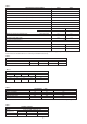
BENCHMARK No. GAS BOILER COMMISSIONING CHECKLIST COLLECTIVE MARK BOILER SERIAL No. CONTROLS NOTIFICATION No.
SERVICE INTERVAL RECORD It is recommended that your heating system is serviced regularly and that you complete the appropriate Service Interval Record Below. Service Provider. Before completing the appropriate Service Interval Record below, please ensure you have carried out the service as described in the boiler manufacturer s instructions. Always use the manufacturer s specified spare part when replacing all controls SERVICE 1 DATE SERVICE 2 DATE ENGINEER NAME COMPANY NAME TEL No.
This manual is to be used in conjunction with the variant part number of the bar code below: www.worcester-bosch.co.uk Bosch Group Worcester, Bosch Group, Cotswold Way, Warndon, Worcester WR4 9SW. Telephone: 01905 754624. Fax: 01905 753130. Technical Helpline 08705 266241. Worcester, Bosch Group is a trading name of BBT Thermotechnology UK Limited.