
Technical data


18
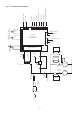
Fig. 34. Programmer cover
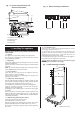
Fig. 35. Facia connections
Fig 36 - Mains Voltage External Controls
Connections
230 V room thermostat and
Programmer Connections
Neutral
Live
Neutral
Live
Switched Live
Motor
1
2
3
1. Programmer connections
2. Boiler outer casing
3. Cover panel
3
4
5
15
ST2
6
Series
connection
point
7
8
9
8
10
11
12
13
14
2
2
1
1. Controls connector cover
2. Controls connector cover fixing screws (2)
3. Facia control panel
4. Earth connection (tags)
5. Earth connection (screws)
6. Cable clamp
7. Fuse F1 2A (slow)
8. Cable clamp
9. ST15 Pump
10. ST1 Fan
11. Fuse F2 1.25A (slow)
12. Code plug
13. Commissioning switch
(gas valve mode switch)
14. Internal controls connectors
15. Mains and external controls connectors
(230 Volt)
ST2
Remove Link
230 V Room Thermostat Connections
Ns Ls LR
ST2
Neutral
Live
Switched Live
Remove Link
spare
Neutral
ST2
Remove Link
Live
Switched Live
Motor
230 V Programmer Connections
Ns LsNLNsLsL
R
spare
Ns LsNL
Ns Ls L
R
spare
Ns LsNL