
Technical data


2524
Plume management system options
Standard plume management system
The flue terminal outlet has built-in stops to limit rotation
for horizontal fluing to allow condensate to run back into
the boiler for safe disposal. Do not attempt to force beyond
the limit stops.
All plume management sections must rise by at least
173mm per metre (10º) from the terminal to ensure that
condensate flows back into the boiler.
500mm (M)
Opening in building
e.g. window
Direction of
flue discharge
Min. 1,500mm
Opening in building
e.g. window
Direction of
flue discharge
Min. 1,500mm
Re-directing flue discharge from a 60mm dia. plume
management outlet
500mm
(min) (M)
L (max)
4,500mm
(max) (M)
L (max)
Fig A
Fig B
Condensfit II telescopic flue and plume management
system measuring
Plume management system
60mm dia. plume management kit
Com
prises:
1 x terminal elbow
1 x extension 500mm
1 x outlet assembly
1 x clamp pack
Part No. 7 716 191 086
Accessories
Effective straight flue lengths for telescopic flue with
plume management
Model Fig. A Fig. B
Max. straight flue Max. straight flue
length (L) with min. length (L) with max.
plume management plume management
length (M)* (mm) length (M)* (mm)
Highflow 440CDi** 4,000 1,200
Highflow 550CDi** 4,000 1,200
NOTE:
Plume management minimum straight length = 500mm
Plume management maximum straight length = 4,500mm
**For every additional 1,000mm of plume management
length (M), reduce flue length (L) by 700mm – see figures
A and B.
1000
1500
2000
2500
3000
3500
4000
500 700 900 1100 1300 1500 1700 1900 2100 2300 2500 2700 2900 3100 3300 3500 3700 3900 4100 4300 4500
Plume management length allowed ‘M’ (mm)
Effective flue length ‘L’ (mm)
Condensfit II telescopic flue and plume management
system measuring
100mm dia. horizontal telescopic flue lengths with a
60mm dia. plume management system
The maximum effective straight flue lengths (L) are stated
opposite for the relevant appliance together with the
minimum and maximum lengths (M) of the plume
management system connected, these lengths must not
be exceeded.
60mm dia. plume management system
To ensure that the maximum total straight flue length along
the plume management route is not exceeded the following
should be added to dimension (M):
•
1,500mm for each extra 90º bend
•
750mm for each extra 45º bend
For plume management options with 60mm dia. extensions
refer to page 26.
Note: For information on the Condensfit II Telescopic Flue
System and Plume Management Kit, please see
dedicated flue Technical and Specification leaflet
8 716 112 174.
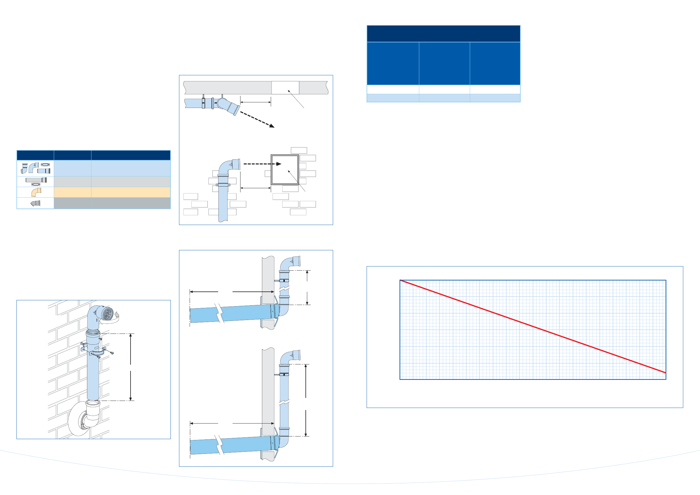
Flue length ‘L’ versus plume management kit
Use the graph above to determine the permissible plume
management lengt
h that can be used with your effective
flue length ‘L’.
The effective flue length can be determined by adding
together all the straight flue lengths and the effective
lengths of the bends used, 1,500mm for each 90º bend and
750mm for each 45º bend.
Components Part no. Description
7 716 191 086
60mm dia.
Plume management kit
7 716 191 087 60mm dia. Extension (1,000mm)
7 716 191 088 60mm dia. 90º Bend
7 716 191 089 60mm dia. 45º Bend (pair)