
Technical data


1514
External condensate pipework
The Worcester Greenstar Highflow CDi appliances have a
condensate pump rather than a syphonic condensate trap.
Rather than the condensate constantly dripping into the
discharge pipe, the condensate is collected in the pump
which releases it in 100ml quantities. This will help prevent
freezing occurring.
Wherever possible the condensate discharge pipework
should be routed and terminated internally. Should this not
be possible, and the only available route is external, the
following conditions should be observed:
•
The pipework length should be kept to a minimum and
the route as vertical as possible
•
Where pipework could be subjected to extreme cold or
wind chill, a weather proof insulation should be used.
Alternatively, the condensate pipework could be
increased to a minimum 32mm.
Compartment installation
The appliance may be installed in any room, although
par
ticular attention is drawn to the requirements of the
IEE regulations applicable and in Scotland the electrical
provisions with respect to installation in a room containing
a bath or shower.
Air supply
1. The room in which the appliance is installed does not
require a dedicated air vent.
2. If the appliance is installed in a cupboard or
compartment with dimensions that allow the following
minimum clearances, then no ventilation is required:
Compartment installation
Position of appliance Min. unventilated clearance
In front 75mm*
Right side 100mm
Left side 100mm
Above flue elbow/casing 50mm
*75mm from an opening door. 600mm is required for servicing
Boiler location and clearances
This boiler is only suitable for installing internally within a
property at a suitable location on a fixed, rigid non-
combustible surface of at least the same size as the boiler
and capable of supporting the boiler weight.
Compartments: Follow the requirements of BS 6798 and
BS 5440 Part 2 and note:
•
Minimum clearances must be maintained
•
An access door is required to install, service and maintain
the boiler and any ancillary equipment
•
If fitting the boiler into an airing cupboard use a non-
combustible perforated material (maximum hole sizes of
13mm) to separate the boiler from the airing space.
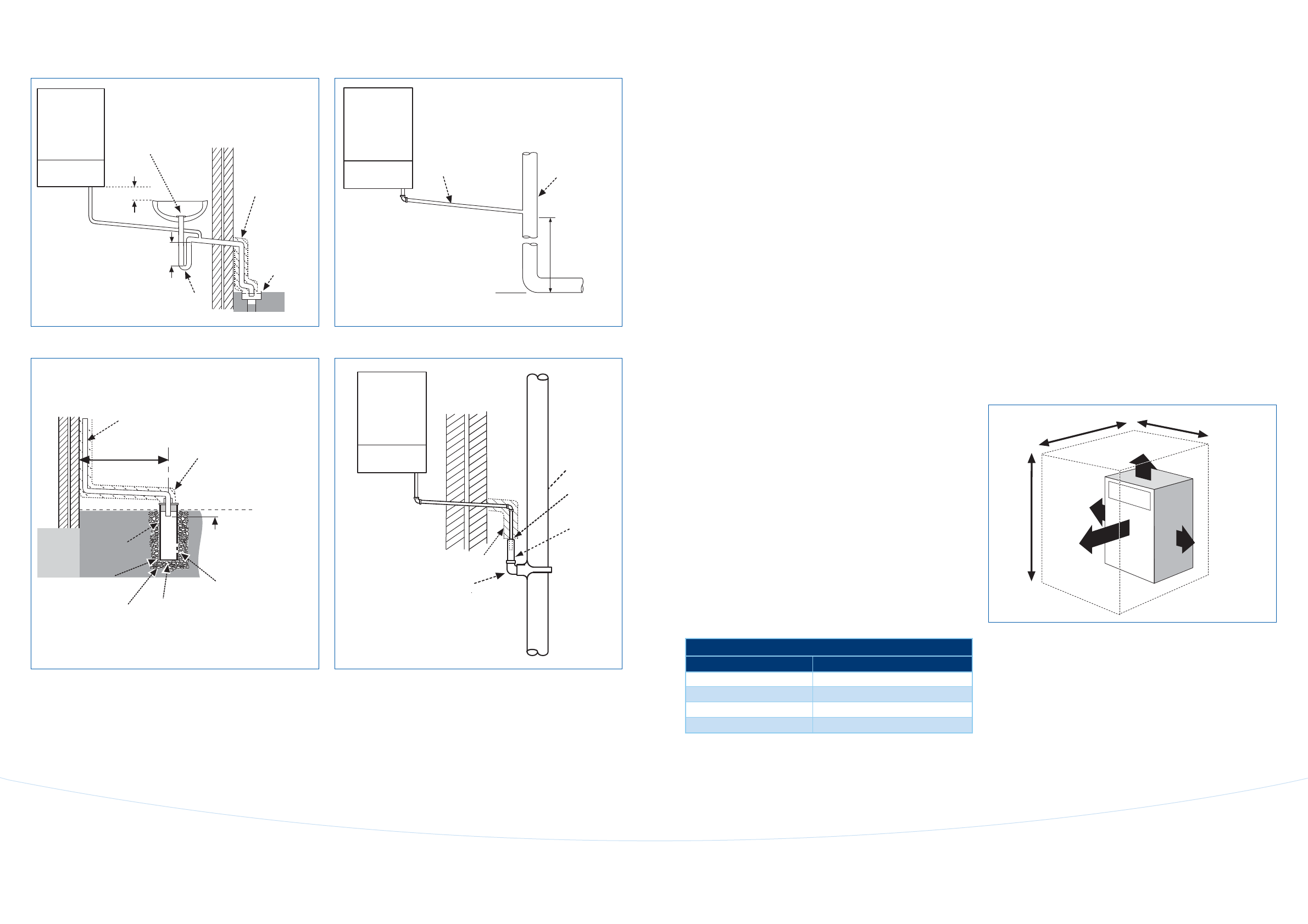
Unvented compartment clearances
The diagram shows the minimum space required to install
and service the boiler inside an unvented compartment.
800mm
800mm
900mm
100mm**
200mm*
100mm**
50mm
*Space required for unvented areas with a removable door or panel.
**This space can be reduced to 50mm for one side only as along as both the side
clearances add up to the total of both the side measurements shown or more.
75 mm
min.
Condensing
boiler
22mm dia.
plastic pipe
75mm sink
waste trap
Open end of
condensate
drainage pipe
directly into
gully below
grating but
above water
level
Visible air break
at plug hole
100mm
Sink with
integral
overflow
Insulation
or increase
pipe size
Internal sink/washing machine drain
Soil & vent stack
22mm dia.
Minimum
450mm
and up t
o
3 storeys
Condensing
boiler
Invert
Soil and vent stack
Condensate drainage
pipe can be run above
or below ground
25mm
Bottom of
tube sealed
Limestone
chippings
Hole depth
400mm min.
by 300mm dia.
Drainage holes
22mm dia. condensate
drainage pipe, max external
length 3 metres
Diameter 100mm
min. plastic tube
500mm min.
Insulation or
increase pipe size
External condensate absorption point (unsuitable for clay soil types)
22mm dia. plastic
condensate drainage
pipe running through
the external wall
External
air break
Air gap
External drain
pipe into foul
water sewer
68mm dia.
PVC-u strap
on fitting
43mm 90°
M & F bend
Condensing
boiler
Insulation or
increase pipe size
External air break when using a foul water down pipe
Condensate termination and route