INSTALLATION, COMMISSIONING AND SERVICING INSTRUCTIONS WALL HUNG RSF GAS FIRED CONDENSING REGULAR BOILER GREENSTAR CDi CLASSIC REGULAR FOR OPEN VENTED AND SEALED CENTRAL HEATING SYSTEMS AND INDIRECT DOMESTIC HOT WATER THE APPLIANCE IS FOR USE WITH NATURAL GAS OR L.P.G.
CONTENTS CONTENTS 1 KEY TO SYMBOLS AND SAFETY PRECAUTIONS . . . . . . . . . . . . 3 1.1 Key to symbols . . . . . . . . . . . . . . . . . . . . . . . . . . . . . . . . . 3 1.2 Safety precautions . . . . . . . . . . . . . . . . . . . . . . . . . . . . . . 4 2 APPLIANCE INFORMATION . . . . . . . . . . . . . . . . . . . . . . . . . . . . . 5 2.1 General information . . . . . . . . . . . . . . . . . . . . . . . . . . . . . 5 2.2 Technical data . . . . . . . . . . . . . . . . . . . . . . . . . . . . . . . . .
KEY TO SYMBOLS AND SAFETY PRECAUTIONS 1 1.1 KEY TO SYMBOLS AND SAFETY PRECAUTIONS KEY TO SYMBOLS WARNINGS Warnings in this document are identified by a warning triangle printed against a grey background. Keywords at the start of a warning indicate the type and seriousness of the ensuing risk if measures to prevent the risk are not taken. The following keywords are defined and can be used in this document: • NOTE indicates a situation that could result in damage to property or equipment.
KEY TO SYMBOLS AND SAFETY PRECAUTIONS 1.2 SAFETY PRECAUTIONS INSTALLATION REGULATIONS IF YOU SMELL GAS Current Gas Safety (Installation & Use) Regulations: A gas leak could potentially cause an explosion. If you smell gas, observe the following rules. All gas appliances must be installed by a competent person in accordance with the above regulations. Failure to install appliances correctly could lead to prosecution. ▶ Prevent flames or sparks: – Do not smoke, use a lighter or strike matches.
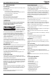
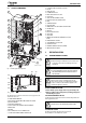
APPLIANCE INFORMATION 2 APPLIANCE INFORMATION 2.1 GENERAL INFORMATION C K D J STANDARD PACKAGE: A Wall hung gas fired condensing regular boiler for central heating and domestic hot water B Wall mounting plate C Hanging bracket D Hardware pack 1 E Hardware pack 2 (gas cock) F Literature pack G Bottom panel H Trap / Siphon Outlet Connection (22mm Plastic Pipe) J Flow pipe K Return pipe 1 L Return pipe 2 M Pipework mounting bracket N Gas cock support plate O Braising template x.
APPLIANCE INFORMATION 2.2 TECHNICAL DATA DESCRIPTION Heating Max. rated heat input Max. rated heat output net 40/30°C Max. rated heat output net 50/30°C Max. rated heat output net 80/60°C Min. rated heat output net 40/30°C Min. rated heat output net 50/30°C Min. rated heat output net 80/60°C Min. rated heat input net Max. flow temperature Max. permissible operating pressure Gas flow rate - Max. 10 minutes from lighting Natural Gas G20 Propane Gas (LPG) Flue Flue Gas Temp. 80/60°C, rated min.
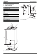
PRE-INSTALLATION 2.3 LAYOUT & COMPONENTS 21 1 2 20 3 19 18 4 17 5 16 15 14 6 10. CONTROL PANEL IN SERVICE POSITION 11. FLOW 12. TRAP/SIPHON 13. CONDENSATE HOSE 14. INLET PRESSURE TEST POINT 15. GAS VALVE 16. AIR / GAS ADJUSTMENT SCREW 17.TESTING POINT FOR FAN PRESSURE 18. FAN 19. PRIMARY SENSOR 20. AUTO AIR VENT 21. REMOVABLE TOP CASE PANEL FOR SERVICING 22. BLANK PLATE 23. DISPLAY 24. FAULT RESET BUTTON 25. NOT USED 26. NOT USED 27. MAINS ON/OFF INDICATOR/DIAGNOSTIC LIGHT (BLUE) 28.
PRE-INSTALLATION ▶ Close drain cocks and add a suitable flushing agent compatible with aluminium at the correct strength for the system conditions in accordance with the manufacturer‘s instructions. The pH value of the system water must be less than 8 or the appliance guarantee will be invalidated. ▶ Circulate the flushing agent before the boiler is fired up. ▶ Run the boiler/system at normal operating temperature as directed by the manufacturer of the flushing agent.
PRE-INSTALLATION 3.3 WATER SYSTEMS & PIPEWORK S AND Y PLAN SYSTEM: PLASTIC PIPEWORK: • Any plastic pipework must have a polymeric barrier with 600 mm (minimum) length of copper or steel pipe connected to the boiler. • Plastic pipework used for underfloor heating must be correctly controlled with a thermostatic blending valve limiting the temperature of the circuits to approx. 50°C. The pipework from the boiler to the blending valve must be in copper or steel (protected from corrosion).
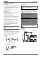
PRE-INSTALLATION Sealed system with two heat zones Y PLAN LAYOUT Y PLAN LAYOUT SEALED SYSTEM LAYOUT 1 8 3 7 8 2 7 150 mm max M M 4 5 M M 5 MCW 10 6720648547-41.1Wo Fig. 6 Y plan Fig. 9 SEALED SYSTEM LAYOUT 12 4 6 11 9 6720648547-28.1Wo Sealed system with two heating zones SEALED SYSTEM LAYOUT 8 7 4 M 5 12 MCW 11 10 Fig. 7 6720648547-42.
PRE-INSTALLATION CONDENSATE PIPE WORK NOTICE: ▶ Where a new or replacement boiler is being installed, access to an internal “gravity discharge” point should be one of the factors considered in determining boiler location. ▶ The condensate pipe must be nominally 22mm Ø plastic pipe. ▶ The condensate pipe work must fall at least 52mm per metre towards the outlet and should take the shortest practicable route. ▶ Ensure there are no blockages in the pipe run.
PRE-INSTALLATION 3.4.2 EXTERNAL CONNECTIONS NOTICE: Freezing conditions ▶ Pipe work length should be kept to a minimum and the route as vertical as possible. ▶ Weather proof insulation must be used. FITTING AN EXTERNAL AIR BREAK • Refer to figure 13 when a rain water down pipe is used to dispose of condensate. • An air break must be installed in the 43mm pipe work, between the boiler condensate outlet and the drainpipe, outside the property, to avoid flooding during adverse weather conditions.
PRE-INSTALLATION Minimum hole size for the condensate soak away must be 400mm deep by 300mmØ . In situations where there are likely to be extremes of temperature or exposure, the use of a proprietary trace-heating system for external pipe work, incorporating an external frost thermostat, should be considered. If such a system is used, the requirement to use 32mm pipe does not apply. However, all other guidance above and the instructions for the trace heating system, should be closely followed.
PRE-INSTALLATION BATHROOMS: Additional RCD (Residual Current Device) protection may be required. Refer to the latest IEE wiring regulations. NOTICE: Any switch or appliance control using 230 V mains electricity must not be able to be touched by a person using the bath or shower. Electrical switches, fused spur and socket outlets must not be situated in the bathroom.
PRE-INSTALLATION 3.6 PLUMBING MANIFOLD CONNECTIONS: Heating System: 22 mm compression fittings Gas: 22 mm compression fittings Use the fittings supplied in the Hardware pack. PREPLUMBING With the plumbing manifold installed, pipe work can be installed to the valves on the manifold. RUNNING PIPES BEHIND THE BOILER If the boiler pipes are to be run behind the appliance ensure that the pipes pass close to the wall as shown in the diagram opposite, and within the pipe guide.
PRE-INSTALLATION 3.7 FLUE TERMINAL POSITIONS All measurements in millimetres 2m 1m 2 25 25 104mm 52mm 16 3 1,500 600 13 400 300 500 12 14 2 200 300 1 5 300 300 1,500 4 7 8 600 500 300 600 300 300 6 9 1,200 15 600 18 600 10 16 11 300 300 300 17 300 300 25 300 Boundary Line 0 672 643 895 -13.3 Wo Fig. 20 Flue terminal positions NOTICE: ▶ All measurements are the minimum clearances required.
PRE-INSTALLATION 3.8 FLUE OPTIONS The Greenstar CDi has the option of three horizontal RSF (60/100 telescopic, 60/100 longer telescopic and 80/125 telescopic) flue systems and two vertical RSF (60/100 or 80/125) regular flue systems: The systems have different maximum flue lengths for different boiler outputs and different plume management lengths.
PRE-INSTALLATION 350 mm - 570 mm 1 130 mm Min 7 2 Pitc h roo ed 500 mm f 300 mm Flat roof 8 3 4 9 5 10 6 18 6720643895-12.
PRE-INSTALLATION 3.9 PLUME MANAGEMENT TERMINAL POSITIONS All measurements in millimetres Flue terminal guard 7 716 191 176 ±45° Plume re-direction: 100 600 1 180° Flue Exhaust Outlet 10 1,500 Air Intake ±80° 6 200 300 2 200 5 600 300 300 3 150 300 300 300 25 200 300 150 1,200 300 8 150 200 7 150 25 600 9 10 150 4 Boundary Line 672 064 389 5-14 o .2W Fig. 21 Plume terminal positions NOTICE: ▶ All measurements are the minimum clearances required.
INSTALLATION 4 INSTALLATION 2 NOTICE: All the previous Pre-Installation sections must be read and requirements met before starting boiler or flue installation. 4.1 K J UNPACKING WALL FRAME AND ANCILLARY ITEMS 2 LIFTING AND CARRYING PRECAUTIONS: B WARNING: ▶ Lift only a manageable weight, or ask for help. ▶ When lifting the boiler, bend the knees, and keep the back straight and feet apart. ▶ Do not lift and twist at the same time. ▶ Lift and carry the boiler close to the body.
INSTALLATION 4.2 WALL MOUNTING PLATE FLUE OPENING CAUTION: Ensure there are no pipes, electric cables, damp proof courses or other hazards before drilling. min. 225 mm 85 mm SAFETY: ** All relevant safety precautions must be undertaken. Protective clothing, foot wear, gloves and safety goggles must be worn as appropriate.
INSTALLATION 4.3 UNPACKING THE APPLIANCE 1. With the wall frame and ancillary items removed, lay the carton (A) on its back. 2. Open the carton bottom flaps and fold under boiler. Do not remove the packaging base. 3. Stand carton (A) with boiler upright on the packaging base (B). 4. Remove outer carton (A) and place safely away from the working area. 5. Remove the protective wrapping (C). 6. Lie the boiler on its back. 7. Remove the packaging base (B) and place safely away from the working area. 1. 2.
INSTALLATION 4.4 FITTING THE APPLIANCE BOILER CONNECTIONS 2 CAUTION: Isolate the mains gas supply before starting any work and observe all relevant safety precautions. GAS AND WATER CONNECTIONS: • If there is greater than 600mm clearance below the appliance it is possible to fit the flow and return pipes, supplied, with the boiler installed on the wall.If clearance is less than 600 mm below the appliance it may be necessary to fit the flow and return pipes before hanging the appliance.
INSTALLATION 4.5 FLUE INSTALLATION HORIZONTAL FLUE (60/100mm diameter) For vertical flues and 80/125mm horizontal flues, please refer to separate Flue Kit instructions. L 570 mm 350 mm Apply silicone lubricant to the sealing surfaces of the flue components to ease assembly of flue components. WALL 85 mm 2 1 6720643895-30.1Wo Fig. 31 Ø60mm PLUME MANAGEMENT KIT (7-716-191-086) replaces the plume deflector in the Ø60/100mm telescopic flue terminal. 4.5.3 ADJUSTING THE STANDARD TERMINAL LENGTH: 1.
INSTALLATION 4.5.4 INSTALLING THE STANDARD FLUE 4.5.5 FLUE TERMINAL PLUME RE-DIRECTION: 1. Set the flue length to the distance required, secure with screw and seal joint with the aluminium tape supplied. Slide the inner wall seal (1) onto the terminal (2) as shown. If fitting from inside the building; slide the outer wall seal (3) onto the terminal (2) as shown.
INSTALLATION 4.7 ELECTRICAL CAUTION: Isolate the mains gas supply before starting any work and observe all relevant safety precautions. 1 Danger of short circuit: When connecting the cables ensure that no cable strands fall into the Heatronic. Mains supply to the boiler must be through a fused double pole isolator situated adjacent to the appliance. The isolator must have a contact separation of 3 mm minimum in all poles.
INSTALLATION 1. The mains supply to the boiler must be fed through a fused double pole isolator situated adjacent to the appliance. The isolator must have a contact separation of 3 mm minimum in all poles. B 2. 8. External Pump (ST2): ▶ Connect NEUTRAL wire to terminal (Nz) ▶ Connect LIVE wire to terminal (Lz) ▶ Connect EARTH wire to earth bracket (E) C 3. 4. The system pump must be connected to the appliance control for the pump over-run facility. 5. D EARTH = LIVE = D NEUTRAL = E 7. 6.
INSTALLATION 4.8 POSITION OF WIRED COMPONENTS PRE WIRED LINK FLAME SENSE ELECTRODE SPARK ELECTRODES FLOW NTC FAN Colour sequence OVERHEAT STAT FLUE OVERHEAT STAT GAS VALVE SAFETY SOLENOID SAFETY SOLENOID MAINS SUPPLY PUMP SUPPLY Earth Neutral Supply Live Supply Live Return Neutral Live 230V EXTERNAL CONTROLS WIRING CENTRE Colour sequence CH TEMPERATURE CONTROL LZ NZ ST2 ST5 LR LS NS N L ST4 ST6 ST10 FR FS NP LP ST8 9 8 7 Fuse F1, slow 2.
COMMISSIONING 5 COMMISSIONING 5.1 PRE-COMMISSIONING CHECKS CAUTION: Isolate the mains gas supply before starting any work and observe all relevant safety precautions. 1. Check that the service and water pipes are connected to the correct position on the manifold. A - CH flow (22mm) B - CH return (22mm) C - Gas inlet (22mm) 2. Check the gas type specified on the identification plate (F) matches that of the gas supply.
COMMISSIONING 4. Drain and thoroughly flush the system to remove the flushing agent and debris. A D F L reset eco 3 E H M 1 6. Fill via a WRAS approved filling loop to between 1 and 2 bar. 7. Vent all radiators; retighten vents when complete. 8. Vent the primary side of the hot water tank. 5 6 max B 6720648547-49.1Wo Fig. 43 Control panel A B C D E F H K L M 5.
COMMISSIONING 5.6 COMMISSIONING CHECKING GAS INLET PRESSURE: The inlet pressure to the appliance must be checked using the following procedure: SETTING THE BOILER TO MAXIMUM: 1. Press performance test button (L) for ten seconds and set temperature to maximum. • The performance test button (L) will illuminate continually. A D F L K reset eco 3 1 Ensure inlet pressure is satisfactory with all other gas appliances working.
COMMISSIONING Refer to the figure below for L.P.G gas pressures. INSTALLING BOTTOM PANEL: The pressure at the boiler must not be less than the pressure read at the meter minus 2.5 mbar. 2. The bottom panel slides onto two ledges (C) either side of the boiler frame. The pressure drop from the meter to the gas valve must not be more than 4mbar for LPG. ▶ Hold the panel up against the underside of the boiler and slide towards the rear until it is fully engaged.
SERVICING AND SPARES 6.1 INSPECTION AND SPARES NOTICE: Any service work must be carried out by a competent registered engineer such as British Gas or Gas Safe. C • To ensure the continued efficient operation of the appliance it must be checked at regular intervals. • The frequency of servicing will depend upon the particular installation conditions and usage. However, an annual service is recommended.
SERVICING AND SPARES COMPONENT ACCESS Adjusting boiler control to service position. Removing outer case 1. Pull down the catch securing the control panel. 2. Gently pull forward until it comes to rest in service position. 1. Remove bottom panel by pulling it forward and off. 2. Undo but do not remove the 2 screws (A) securing boiler casing at the bottom of the appliance. 3. Pull upwards to release the clip (B) on top of the boiler. 4. Pull case forward and remove. 1. 2. 6720648547-45.1Wo 1. Fig.
SERVICING AND SPARES 6.1.1 FAN PRESSURE TEST This test is to determine if the heat cell requires cleaning/ attention • Pressure readings in the black area will indicate that the heat exchanger requires attention/cleaning. • There is a special accessory kit available specifically designed for cleaning the heat exchanger. Part number 7 719 001 996. FAN PRESSURE TEST SET THE BOILER TO MAXIMUM Clean the Heat Ex. - 5.2 40 CDi: - 4.
SERVICING AND SPARES 2. Loosen any deposits in the heat exchanger from top to bottom using the cleaning blade. 1. B A B 2. 6720647361-63.1Wo 2. Remove the clips (C) and unscrew the two bolts (D). ▶ Unscrew and remove the two hexagon screws (E) securing the fan. ▶ Slacken fully the rear securing bolt (F). ▶ Remove the burner cover plate (G). 6720803599-03.1Wo 3. Clean the heat exchanger from top to bottom using the brush. F 2. C D 3. 6720647361-64.1Wo 3.
SERVICING AND SPARES ▶ Adjust air/gas ratio. Refer to section 6.2 “Setting the air/gas ratio”. J 4. 3. Using a flat blade screwdriver set the CO2 via the max adjuster referring to the table below. K CO2 should be measured 10 minutes after firing the appliance. 6720647361-66.1Wo I The control will resume normal operation after 15 minutes or if the performance test button is pressed for over a second. 6.1.5 TO CLEAN THE CONDENSATE TRAP 1. Pull condensate pipe out of the adaptor. 2.
SERVICING AND SPARES 1. Max adjust Min adjust 4mm 3. 2. Inlet pressure test point 6720647361-48.1Wo A B Fig. 57 Setting the Air/Gas ratio 6.3 REPLACEMENT OF PARTS 4. CAUTION: Isolate the mains gas supply before starting any work and observe all relevant safety precautions. 6720647361-27.4Wo NOTICE: After replacement of any components always check for gas tightness where relevant and carry out functional checks as described in commissioning.
SERVICING AND SPARES Primary sensor ▶ Press retaining clip on plastic moulding and pull upwards until clear of pocket in heat exchanger. ▶ Separate sensor from connector, coat new sensor with heat conductive paste and replace. ▶ Remove two electrical connectors from thermostat. ▶ Unscrew the sensor. Flue limit thermostat ▶ Remove electrical connections. ▶ Unscrew thermostat from flue. Overheat thermostat 3. 4. 6720648547-29.2Wo 5. Fig.
SERVICING AND SPARES 7. GAS VALVE A ▶ Isolate gas supply at boiler gas cock. ▶ Pull out air inlet tube (A). ▶ Undo top gas connection (B) to gas valve. ▶ Undo bottom gas connection (C) to gas valve. ▶ Undo two securing screws (D)on the underside of casing. ▶ Pull valve up and forward out of boiler. ▶ Disconnect electrical connections. ▶ Replace valve with new seals and check for gas soundness. 9. The valve will require setting, follow procedure “Setting the gas/air ratio” in the gas conversion section.
SERVICING AND SPARES 11. PCB REMOVAL 12. FAN ASSEMBLY To gain access to the PCB: ▶ Remove the five screws shown in the diagram below and remove the PCB cover. NOTICE: Air/Gas ratio ▶ After re-assembly the combustion must be checked using the procedure in the section “Setting the air/gas ratio.” ▶ The setting of the gas ratio must be carried out by a competent person.
SERVICING AND SPARES 13. ELECTRODE ASSEMBLY WARNING: Electrode gasket ▶ Do not remove the electrode assembly unless a new gasket is available for re-assembly. F 2. C D ▶ Disconnect spark electrodes and flame sensor connection. ▶ Remove two screws (F). ▶ Remove spark/flame electrode assembly (G) from heat exchanger. ▶ Inspect the spark/flame electrode assembly and ceramics for signs of contamination or damage, replace as necessary.
SERVICING AND SPARES 15. BURNER D 3. ▶ Remove the burner (H). ▶ Replace new burner in correct position. ▶ Ensure that a new seal (K) is used, refer to fig. 70. C 8. H 6720647361-69.1Wo 6720647361-49.2Wo Fig. 74 Heat exchanger removal 3 4. Undo flue connection (E) from sump (F). ▶ Pull flue pipe up. ▶ Remove the heat exchanger. 4. Fig. 71 Burner removal E 16. HEAT EXCHANGER ▶ Isolate flow and return valves and drain the boiler. ▶ Remove condensate trap (see page 40).
SERVICING AND SPARES 6.4 SHORT PARTS LIST Fan Burner 8 717 204 453 0 8 718 006 658 0 GC No. H26 536 GC No. E27 200 4 Burner skin seal Gas valve 8 711 004 166 0 8 718 221 347 0 GC No. E27 201 GC No. H56 469 Temperature limit sensor 6 Electrodes 8 722 963 858 0 8 718 107 089 0 GC No. H08 291 GC No. H22 458 Control sensor - primary Flue overheat thermostat 8 714 500 087 0 8 710 506 267 0 GC No.
FAULT FINDING & DIAGNOSIS 7 FAULT FINDING & DIAGNOSIS 7.1 FAULT FINDING PRELIMINARY CHECKS: Preliminary electrical system checks are the first electrical checks to be carried out during a fault-finding procedure. On completion of the Service/Fault-Finding task which has required the breaking and remaking of electrical connections, check: This fault finding information is for guidance only. Worcester Bosch cannot be held responsible for costs incurred by persons not deemed to be competent.
POWER SWITCH ON BLUE LIGHT ON Room thermostst and/or mains programmer ON (or link fitted at ST10) AND Facia mounted programmer (if fitted) ON AND CH control knob ON 46 LOCKOUT YES 5th attempt? NO Stop spark. wait 10 seconds NO BURNER LIT? IGNITION SEQUENCE IGNITION SEQUENCE (see details) Spark ignition 4 seconds Fan to start speed. GREEN FLAME LIGHT ON YES 10 seconds stabilisation period.
NOTES 6 720 648 547 (2012/06) 47
6 720 648 547 (2012/06)
6 720 648 547 (2012/06) 49
Failure to install and commission according to the manufacturer’s instructions and complete this Benchmark Commissioning Checklist will invalidate the warranty. This does not affect the customer’s statutory rights.
Service Record It is recommended that your heating system is serviced regularly and that the appropriate Service Interval Record is completed. Service Provider Before completing the appropriate Service Record below, please ensure you have carried out the service as described in the manufacturer’s instructions. Always use the manufacturer’s specified spare part when replacing controls. Service 1 Date: Service 2 Date: Engineer Name: Engineer Name: Company Name: Company Name: Telephone No.
WORCESTER, BOSCH GROUP: Worcester, Bosch Group Cotswold Way, Warndon, Worcester WR4 9SW. Tel. 0844 892 9900 Worcester, Bosch Group is a brand name of Bosch Thermotechnology Ltd. worcester-bosch.co.