
Technical data


PRE-INSTALLATION
6 720 648 547 (2012/06) 9
3.3 WATER SYSTEMS & PIPEWORK
PLASTIC PIPEWORK:
• Any plastic pipework must have a polymeric barrier with 600 mm
(minimum) length of copper or steel pipe connected to the boiler.
• Plastic pipework used for underfloor heating must be correctly
controlled with a thermostatic blending valve limiting the temperature
of the circuits to approx. 50°C.
The pipework from the boiler to the blending valve must be in copper
or steel (protected from corrosion).
CONNECTIONS/VALVES:
• All system connections, taps and mixing valves must be capable of
sustaining a pressure up to 3 bar.
• Radiator valves should conform to BS2767:10.
• Do not use galvanised pipes or radiators.
• All other valves should conform to BS1010.
• On new installations, or extensions to existing systems where a
radiator previously did not exist, each radiator should be fitted with a
TRV, except the one fitted in the same room/area as the room
thermostat.
• On boiler only replacement jobs, it is recommended, (but not
mandatory,) to fit a TRV on each radiator. It is, however, a
requirement, for energy conservation purposes, to recommend to the
customer that a TRV is fitted to each radiator.
• An automatic bypass may be required, (downstream of the pump), in
order to maintain the minimum flow-rate through the appliance.
• An air vent is required at the highest point on the system.
SEALED PRIMARY SYSTEM:
• The CH sealed system must be filled using a WRAS approved filling
loop or comply with figure 4 for system fill.
• An expansion vessel, of a size suitable for the system, must be fitted
as close as possible to the appliance in the central heating return.
• Also fit a pressure gauge, a 3 bar pressure relief valve and stop cock
(fixed cylinder type or sealed system approved connection).
• Do not use galvanised pipes or radiators.
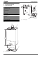
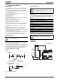
SYSTEM FILL
Fig. 4 System fill/System make-up
S AND Y PLAN SYSTEM:
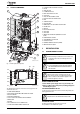
SYSTEM LAYOUT:
S PLAN LAYOUT
Fig. 5 S plan
NOTICE: Artificially softened water must not be used to
fill the central heating system.
SYSTEM FILL
CV = Check Valve
SV = Stop Valve
SV SV
Test point
Temporary hose
Hose union
CV
CV
Heating
return
Mains
supply
SYSTEM MAKE UP
AA = Auto Air vent
CV = Check Valve
SV
CV
AA
Make up
vessel
Heating
return
1000 mm (39 in)
above the highest
point of the system.
Fill point
6720644743-08.1Wo
NOTICE: Bypass
▶ Generally a bypass is not necessary on a Y plan system
as one of the ports is open to flow.
1 Static head -
Minimum static head 250mm measured from the highest
point in the heating system (top surface of the appliance or
the highest point in the heating system) to the water level in
the feed and expansion tank
2 Heating vent (22mm minimum)
3 Primary cold feed (15mm minimum)
4 Diverter/Zone valve
5 Pump, maximum power 90 Watts
6 Automatic bypass
7 Radiator valve (Flow)
8 Lock shield valve (Return)
9 Expansion vessel
10 Pressure gauge
11 3 bar pressure relief valve
12 Stop cock
Table 4 Key to figures 6, 7, 8 & 9
NOTICE: A drain cock should be fitted at the lowest
point of the heating circuit and beneath the appliance.
S PLAN LAYOUT
8
7
1
3
2
4
6
5
150 mm
max
M
M
6720648547-40.1Wo