Installation and Servicing Instructions R29 & R40 HE conventional Wall mounted condensing boiler for central heating 6 720 610 577-01.10 6 720 611 445 GB (03.
Contents Contents Safety precautions 3 Symbols 3 1 1.1 1.2 1.3 1.4 1.5 1.6 1.7 1.8 1.9 Details of the appliance EC Declaration of Conformity Standard package Description of appliance Accessories Casing dimensions Layout of appliance Function Electrical wiring diagram Technical data 4 4 4 4 5 5 6 7 8 9 2 Installation regulations 11 3 3.1 3.2 3.3 3.4 3.5 3.6 3.7 3.8 3.8.1 3.8.2 3.8.
Safety precautions Safety precautions If you smell gas B Turn off gas service cock at the meter. B Open windows and doors. B Do not operate any electrical switches. B Extinguish any naked flames. B Telephone your gas company. If you smell fumes from the appliance B Switch off appliance (see page 24). B Open windows and doors.
Details of the appliance 1 Details of the appliance 1.3 Description of appliance • Wall-mounted appliance 1.1 EC Declaration of Conformity • Natural gas models are low-emission appliances This appliance is in accordance with the applicable requirements of the Gas Appliance Directive, Boiler Efficiency Directive, Electromagnetic Compatibility Directive and the Low Voltage Directive.
Details of the appliance 1.4 Accessories diameter) for flue lengths up to 13m (R 29 HE ) or 10m (R 40 HE) and vertical flue systems for flue lengths up to 13.7 m (R 29 HE) or 10.7m (R 40 HE). Fitting instructions are sent with these kits. • Standard horizontal flue kit at 100 mm outside diameter for flues up to 4 m in length (3.5m for the R 40 HE). • Flue duct kits for horizontal (125 mm outside 1.
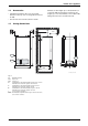
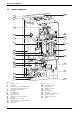
Details of the appliance 1.6 Layout of appliance 120 221.1 221.2 226 102 27 32.1 29 36 271 6 415 43 9 63 416 358 64 423 4.4 7 15 361 295 4 417 Fig. 2 4 4.4 6 7 9 15 27 29 32.
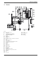
Details of the appliance 1.7 Function 4.4 361 Fig. 3 4 4.4 6 7 9 13 15 27 29 29.1 30 32 33 35 36 43 45 47 52 52.
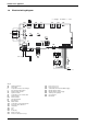
Details of the appliance 1.8 Electrical wiring diagram o - orange bl - black r - red 33 365 364 61 366 363 367 ECO 4.1 25 V 153 230V/AC 230 V 136 310 135 312 328 302 313 151 124 789 L N Ns Ls LR 161 300 9 6 M r r mains supply o 226 52 4.4 52.1 56 o bl bl bl bl 36 32 6 720 610 601-03.2O Fig. 4 4.1 4.4 6 9 32 33 36 52 52.
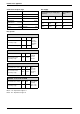
Details of the appliance 1.9 Technical data Units R29 HE Natural gas R29 HE Propane R40 HE Natural gas R40 HE Propane kW kW kw 29.3 29.0 27.4 29.3 29.0 27.4 41.4 41.4 39.1 41.4 41.4 39.1 Max. rated heat input net kW 27.7 27.7 40 40 Min. rated heat output net 40/30°C Min. rated heat output net 50/30°C Min. rated heat output net 80/60°C kW kW kW 8.4 8.3 7.4 11.6 11.4 10.5 12.9 12.8 11.4 16.2 16.1 14.3 Min. rated heat input net kW 7.6 10.8 11.8 14.8 4.2 - Max.
Details of the appliance Gas supply Condensate analysis, mg/l Ammonium 1.2 ≤ 0.01 Lead Nickel 0.15 Mercury ≤ 0.0001 Cadmium ≤ 0.001 Sulphate Chromium ≤ 0.005 Zinc ≤ 0.015 Tin ≤ 0.01 Halogenated hydrocarbons ≤ 0.002 Hydrocarbons 0.015 Vanadium Copper 0.028 pH-value 1 Total length of gas supply pipe (metres) 3 6 Pipe diameter (mm) 9 Gas discharge rate (m3/h) 8.7 5.8 4.6 22 18.0 12.0 9.4 28 ≤ 0.001 4.
Installation regulations 2 Installation regulations Gas Safety (Installation & Use) Regulations 1998: All gas appliances must be installed by a competent person. Failure to install correctly could lead to prosecution. The manufacturers notes must not be taken, in any way, as overriding statutory obligations.
Installation Some plastics are permeable to oxygen and must be avoided, a pipe with a polymer barrier should be used. tee. The pH value of the system water must be less than 8 or the appliance guarantee will be invalidated. Sealed System Suitable products are available from Betz-Dearborn Tel: 0151-4209563 and Fernox Tel: 01799-550811. A sealed system must include an expansion vessel, pressure gauge and pressure relief valve set to operate at 3 bar - these are available as proprietary kits.
Installation AUTOMATIC AIR VENT DOMESTIC HOT WATER CYLINDER RADIATOR RADIATOR RADIATOR RADIATOR DIVERTER VALVE SAFETY VALVE PRESSURE GAUGE PUMP EXPANSION VESSEL BOILER TO SYSTEM FILLING DEVICE DRAIN COCK TYPICAL FULLY PUMPED SEALED SYSTEM Fig. 6 Fig. 7 3.3 Siting the appliance and fitted furniture. The specified clearances must be maintained. Regulations concerning the Installation Site B Relevant national regulations must be complied with section 3.8.1.
Installation 3.4 Wall mounting frame assembly B Take the wall mounting frame out of the package and screw together with 6 screws as shown in fig. 8. Use the inner lugs on the top and bottom horizontal sections. B Screw the pre-plumbing manifold with two screws to the wall mounting frame. 6 720 610 576-11.1O Fig. 10 6 720 610 576-04.1O 3.5 Pre-piping the system Fig. 8 200 B Hold the wall-mounting frame against the wall ensuring that it is vertical.
Installation Condensate Termination and Route The appliance has a built-in syphonic condensate trap eliminating the need for external traps. Connect to the 22mm plastic drain pipe and extend the pipe run away from the control panel and appliance witha constant fall of 2.5° or 25mm in every metre. See Fig. 13.
Installation Fixing the appliance 3.7 B Fit the washers onto the gas and water connections. Water connections B Lift the boiler onto the wall-mounting frame. The lugs pass through the rectangular holes in the boiler back panel. B Take care not to disturb the washers on the connections. Connecting the flue assembly B Fit flue duct connector onto appliance flue spigot. B Secure with the screws supplied. B Turn on the service valves for boiler flow and return. B Check all seals and unions for leaks.
Installation 3.8.1 lighting, activated by passive infra-red sensing heads. If the terminal is less than 2 m above a surface to which people have access then a guard must be fitted. The guard must be evenly spaced about the terminal with a space of 50 mm in each direction and fixed with plated screws. A guard Type K6 for the standard horizontal flue, can be obtained from Tower Flue Components, Vale Rise, Tonbridge TN9 1TB.
Installation 3.8.2 Installation of the flue The standard 100 mm diameter horizontal flue system is suitable for lengths up to 4m (R29) & 3.5m (R40). Flues up to 650 mm do not require an extension duct assembly. Flues between 600 mm and 4000 mm (3500 mm R40) require extension duct assemblies. NOTE: Flue lengths between 650 mm and 730 mm cannot be accommodated. Refer to fig. 18, 19, 20.
Installation Maximum 1600mm Outer Wall Flue Turret Extension Duct Clamp Terminal Assembly 6 720 610 599 - 00.TD Fig. 19 Flue with one extension Outer Wall Flue Turret Clamp Extension Duct Clamp Extension Duct Clamp Terminal Assembly 6 720 610 599 - 01.TD Fig. 20 Flue with extensions Flue Turret Clamp Flue Terminal Extension Flue Duct Wall Sealing Gasket 6 720 610 599 - 01.TD Fig. 21 Flue components 3.8.3 Flue duct preparation and assembly Measure the flue length L. Refer to fig.
Installation The assembly will be made easier if a solvent free grease is lightly applied i.e Silicone lubricant, to the male end of the ducts. L NOTE: An inner wall sealing plate is provided which should be fitted to the ducts before assembly. Push the assembly through the wall and fix the turret to the appliance using the screws provided. Refer to fig. 25. 120 6 720 610 599 - 01.TD Flue Turret Fig.
Electrical connections 4 Electrical connections B Remove screw and slide terminal cover forwards to remove. Refer to fig. 27. B Always disconnect the power supply to the appliance at the mains before carrying out any work on the electrical systems and components. 3 0 4 2 5 1 E All control and safety systems are built into the appliance. B Allow mains cable to protrude at least 50 cm from wall.
Electrical connections 4.2 Wiring to your system Mains electricity supply: The boiler should be connected to the permanent mains supply as described in section 4.1 This also provides the electrical supply to the system. Y-S-Module Note: This must be the only electrical supply to the system. This ensures the safety of a single fused supply. LR LS NS PE PE DV LS NS The boiler can only be wired to a remote system junction box. Note: A pump is not built into the boiler and must be fitted externally.
Commissioning 5 Commissioning 27 136 365 61 317 366 367 358 ECO 364 363 135 E 310 295 15 361 170 170 172 6 720 611 137-11.1O Fig.
Commissioning To drain the appliance shut the system valves and open the drain valve. Suitable flushing agents and inhibitors are available from Betz-Dearborn Tel: 0151-4209563 and Fernox Tel: 01799-550811. Instructions for use are supplied with the these products. B Before commissioning, the gas supply pressure must be checked at the gas supply pressure test point (see page 6, fig. 2, item 7). Natural gas appliances must not be operated if the gas supply pressure is below 18 mbar or above 24 mbar.
Commissioning 5.6 i Fault Condition A list of faults that may occur is given on page 40. In the unlikely event of a fault occurring while the appliance is in operation: The display then shows a fault code and the button may also flash. If the button flashes: B Press and hold the button until the display shows “– –”. The appliance will then start up again and the display will show the boiler flow temperature.
Individual settings 6 Individual settings 6.1 Mechanical settings 6.2 Settings on the Bosch Heatronic 6.1.1 Setting the boiler flow temperature 6.2.1 Operating the Bosch Heatronic The central heating flow temperature can be set to between 50°C and 88°C. The Bosch Heatronic enables easy setting and checking of a large number of appliance functions. Limited maximum setting for low-temperature operation This description is limited to those functions required for commissioning.
Individual settings Entering a setting B To enter the setting for a function, turn the function control. B Press and hold the and buttons simultaneously until the display shows = =. The and buttons will light up. Storing a setting B Level 1: press and hold the play shows [ ]. button until the dis- B Level 2: press and hold the and buttons simultaneously until the display shows [ ]. 6 720 611 137-15.1O After completing the settings B Reset the temperature controls control to their original positions.
Individual settings 6.3 Setting the gas/air ratio The appliance is set at the factory and adjustment to the CO2 settings (gas/air ratio) is only required where the appliance has been stripped down and assembled or if the fan, burner or gas valve are replaced or the appliance has been converted to a different gas type, see section .7 28 6 720 611 445 GB (03.
Converting the appliance to different gas types 7 Converting the appliance to different gas types The setting is factory sealed at maximum. Adjustment to the rated heat input and min. heat input is not necessary. Checking the gas supply pressure B Check the gas supply pressure at the gas supply pressure testing point. i Natural gas appliances must not be operated if the gas supply pressure is below 18 mbar or above 24 mbar.
Converting the appliance to different gas types B Turn the function control until the display shows 2. (= max. rated heat output). The display and the button will flash. B Remove the seal from the gas valve adjusting screw (64) and adjust the CO2 level to the figure given in Table 13 for min. rated heat output. 64 6 720 611 137-20.1O Fig. 42 B Measure the CO2 level. B Prise off the seal on the gas flow restrictor. B Adjust the gas flow restrictor (63) to obtain the CO2 level given in Table 13.
Converting the appliance to different gas types 7.2 Testing combustion air/flue gas at set heat output 7.2.1 Testing the O 2 or CO2 level in the combustion air i By testing the O2 or CO2 level in the combustion air the gas tightness of a type C13 or C33 flue system can be checked. The O2 level must not be less than 20,6 %. The CO2 level must not exceed 0,2 %. B Press and hold the button until the display shows – –. “Chimney sweep” mode is now active.
Maintenance 8 Maintenance B Always disconnect the appliance from the electrical power supply (fuse, circuit breaker) before carrying out any work on the electrical systems or components. B Always turn off the gas cock before carrying out any work on components which carry gas. i There is a special Service booklet for the Engineer, order no. 7-181-465-346, available to competent persons. i All safety and control systems are monitored by the Bosch Heatronic.
Maintenance 8.1 Pre-Service Check List Date 1 Call up the last fault stored by the Bosch Heatronic, Service Function .0, (see page 34). 2 Check ionisation current, Service Function 3.3, (see page 34). 3 Perform visual check of air/flue duct.Visual check of diaphragm for soiling and splits (see page 36). 4 Check gas supply pressure (see page 29). 5 Test combustion air/flue gas (see page 31). 6 Check CO2 setting for min./ max. (gas/air ratio) (see page 29). mbar min. % max.
Maintenance 8.2 Description of servicing operations The combustion performance must be checked before and after any servicing work on the combustion and burner components. Refer to section 7.1. B Unscrew condensation trap and place suitable container underneath. Refer to fig. 48. B Remove the fan and the burner as described in the text headed “Burner” (see page 35). Check “Last fault stored”: B Select Service Function .0 (see page 26 “Selecting service function”).
Maintenance B Clean out the condensate collector and trap connection (with other end of brush). 6 720 610 332-75.2R Fig. 51 B Refit the clean-out cover using a new seal and tighten screws to torque of approx. 5 Nm. Burner B Check that the gas cock is turned off and the master switch is in the OFF position. B Remove the clips (1.) and unscrew the two bolts (2.). Refer to fig. 52. B Unscrew and remove the two hexagon screws securing the fan (3.). 7 181 465 330-09.2R Fig.
Maintenance B Refit and prime the siphon. Diaphragm in mixer unit Take care not to damage diaphragm (443) when removing and refitting it. B Open mixer unit (29). B Carefully withdraw diaphragm (443) from fan intake tube and check for soiling and splits. Condensate Drain Siphon 3. Drain plug 443 29 6 720 611 137 - 23.1O Fig. 55 Electrical wiring 1. B Check the electrical wiring for physical damage and replace any damaged wires. 2. 6 720 610 790-07.2R Fig.
Maintenance 8.3 B Remove the pcb control board. Replacement of Parts Before changing any components check that the gas is turned off and that the appliance is electrically isolated. When necessary close the system valves and drain the appliance. Refitting is a reverse of the procedure for removal using new seals or o-rings as appropriate. 8.3.1 PCB control board and transformer B Switch off the appliance. B Disconnect appliance from the power supply. B Unplug all connectors from the control box (inc.
Maintenance 8.3.2 Fan Assembly 8.3.4 3. Gas Valve B Check that the gas cock is turned off. B Lower the control panel. Refer to fig. 59. 2. 1. 1. 4. 6 720 611 137- 25.1O 2. B Pull off the solenoid connections at the rear of the valve. B Undo the union, within the inner casing, securing the valve to the gas/air tube. Refer to fig. 58. B Remove the white plastic cap from the gas valve. B Release the gas inlet union at the manifold assembly.
Maintenance B Undo the central heating flow union. B Undo the grey plastic cap at the base of the heat exchanger. B Unscrew and remove the condensate trap. Refer to section 8.2. B Unscrew and remove the two screws securing the heat exchanger top bracket to the rear panel. B Lift up the flue duct, item 271, refer to fig. 2. B Pull forward from the top and lift the heat exchanger from the casing. B Transfer components, as necessary, to the new heat exchanger.
Appendix 9 Appendix 9.1 Fault Codes More detailed fault finding procedures are described in the Service booklet for the Engineer number 7 181 465 346. Display code Description Remedy b1 Code plug not detected. Insert code plug correctly, test and replace if necessary. C1 Fan speed too low. Check fan lead and connector, and fan; replace as necessary. d3 Jumper 8-9 not detected. Connector not connected, link missing, underfloor heating limiter tripped.
Appendix 9.2 Short parts list Key Description Qty GC Spare part number 1 Sensor - Flue gas temp. 1 8 729 000 144 0 2 Sensor - boiler flow temp.
Yes * Minimu m heat input for 15min. No Boiler operates to ma tch system load and temperature control setting. Ignition sequence Ignition spark for 5 seconds. Burner lights. Red light ON. Yes Heat demand satisfied. Gas va lve closes. Red light OFF. No 6 720 611 445 GB (03.11) Repeats 5 times (N.G.) or 3 times (L.P.G.) before lock out Fan runs to purge gas from burner. * NOTE : The sequence ensures that the condensate siphon is not empty after long OFF periods.
Appendix 6 720 611 445 GB (03.
Appendix EXCELLENCE COMES AS STANDARD Manufactured exclusively for British Gas by The Bosch Group Bosch Group, Worcester Heat Systems, Cotswold Way, Warndon, Worcester WR4 9SW.