
Technical data

36
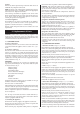
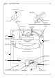
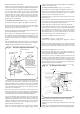
Fig. 35. Inner casing assembly.
Fan outlet
Venturi connections
Fan assembly
Venturi housing
located in fan
outlet
Securing clip
Thermostat
pocket
Safety temperature
limiter thermostat
phial
Water to water
heat exchanger
Flexible pipes (2)
Automatic
air vent
Fan assembly
mounting plate
Gas to water
heat-exchanger
Inner casing
Burner
assembly
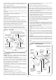
Inner casing flexible
pressure connection
Burner assembly
fixing screws (2)
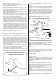
Spark electrodeSpark electrode Pilot pipe Spark electrode lead
Pilot tube sealing
grommet
Pilot pipe union
nut
Sealing cover and
fixing screw
Pilot bracket and
fixing screws (2)
Fan electrical
connections (2)
Thermostat
fixing
Fan assembly
Flue hood
Fan assembly fixing
screws (2)
Flue hood fixing
screws (2)
Combustion chamber cover
Combustion chamber
cover fixing screws (4)
–+