
Technical data

bracket located in the control box.
Release the strain relief bush by compressing the loose
section of the bush and carefully withdraw the leads from the
control box. Remove the high limit thermostat and discard.
Fit a new high limit thermostat using the original fixing
screws in the reverse order. Apply a smear of heat sink
compound to the contact surface. Ensure the leads are
connected to the control board and earthing bracket
correctly. Replace the strain relief bush. Reassemble the
appliance in the reverse order.
16. Heat Bank Overheat Thermostat. See Figs. 9, 16, 40, 53 and 54.
Check that the electricity supply to the appliance is turned off.
Remove the cabinet front panel and place the facia and control
box in the Service Position, as described in Section 14.2 a and b.
Remove the facia as described in Section 15.1.
Remove the spring clip from the thermostat pocket located on
the front left hand side of the heatbank.
Note: There are two thermostat phials fitted in the pocket. The
Heat Bank Overheat Thermostat phial is located at the rear of
the pocket. To identify the phial follow the capillary from the
thermostat body inside the control box to the thermostat
pocket.
Ease the first phial clear of the pocket and place to one side. Ease
the overheat thermostat phial clear of the pocket and unclip the
capillary from the left hand side of the cabinet panel.
Unscrew the two screws on the underside of the control box
securing the mounting bracket holding the Hot Water and
Heating thermostats to the control box. To access the Heat Bank
Overheat thermostat ease this bracket sufficiently clear of the
control box allowing the capillary tubes to feed through the slot
in the rear of the control box.
Ease off the two electrical connections from the rear of the
thermostat. Unscrew the central clamping nut. Withdraw the
overheat thermostat and thread the capillary through the hole in
the left hand side of the control box. Discard the thermostat.
Fit a new thermostat and re-assemble in the reverse order. The
capillary of the replacement thermostat must be uncoiled to
assist its passage through the hole in the control box. Ensure the
capillary is reclipped to the left hand side panel, clear of any hot
surfaces and without tight bends. The spring clip must be
replaced into the thermostat pocket.
Ensure the electrical connections are made to the terminals
inside the control box, polarity is not important. Apply a smear
of heat sink compound to the thermostat phial. Reassemble the
appliance in the reverse order.
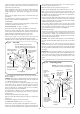
17. Air Flow Pressure Switch. See Figs. 9, 35, 43 and 53.
Check that the electricity supply to the appliance is turned off.
Remove the cabinet front panel and place the facia and control
box in the Service Position, as described in Section 14.2 a and b.
Remove the facia as described in Section 15.1.
Carefully pull off the suction tubes and the electrical connections
from the switch.
Note the position of the suction tubes and electrical connections.
Unscrew the two fixing screws from the bottom right hand side
of the control box securing the air pressure switch.
Remove air pressure switch from the control box and discard.
Fit the replacement switch in reverse order. Ensure the electrical
connections have been made to the correct terminals (Brown to
“C” tag, White to “NC” and the Grey to “NO”) and the suction
tubes fitted to the correct connections on the switch. Connect
Tube marked positive (+) to the connection marked “H” and the
tube marked negative (-) to connection marked “L”.
Reassemble the appliance in the reverse order.
18. Gas Valve. See Figs. 9, 16, 35 and 44.
Check that the electricity supply to the appliance is turned
off.
Remove the cabinet front panel, place the facia and control
box in the Service Position and lower the expansion vessel
into the Service Position as described in Section 14.2 a, b and
c.
Turn off the gas supply at the service cock.
Disconnect the pilot pipe at the gas valve. Unscrew the
bracket supporting the domestic drain from the left hand side
of the gas valve. Retain bracket and screw.
Unscrew the four M4 extended hexagon headed screws
securing the outlet flange connection to the side of the of the
gas valve. Unscrew the inlet gas union at the gas service
cock. Support the valve and unscrew the retaining screws
from the solenoid electrical connection plugs and pull each
plug off its respective set of terminals.
NOTE: The plugs are dissimilar and not inter-changeable.
Pull off the pressure compensating tube.
Remove the gas valve and flange sealing washer clear of the
appliance.
Remove the female half of the brass union connector fixed to
the gas valve inlet. Discard the gas valve and sealing washer.
39
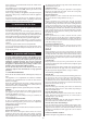
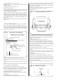
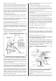
Slacken the fixing
screws and ease the
thermostat body anti-
clockwise to release.
The thermostat body
incorporates fixing
slots, it is not necessary
to remove the screws.
Enlarged detail
Hot water high limit
thermostat
Hot water outlet to
taps
Top manifold assembly
Fig. 42. Hot water high limit thermostat.
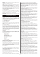
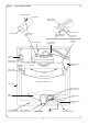
Control box
Suction
tubes (2)
Air flow
pressure
switch
Fixing screws (2)
Safety temperature
limiter thermostat
Fig. 43. Air flow pressure switch.