
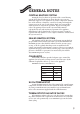
Technical data

Gas Safety (Installation and Use) Regulations 1984 : All gas appliances must be installed by a
competent person, in accordance with the above regulations. Failure to install the appliance
correctly could lead to prosecution. The manufacturers notes must not be taken, in any way,
as overriding statutory obligations.
IMPORTANT: Read these instructions carefully in order to get the best from your appliance.
WARNING: This appliance must be earthed and protected by a 3A fuse if a 13A plug is used, or, if
any other type of plug is used, by a 5A fuse either in the plug or adaptor or at the distribution
board.
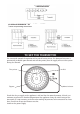
24 hour single channel mechanical timeswitch. User maintenance is not possible.
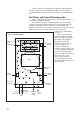
CONTROL
Any number of ON and OFF periods can be chosen within a 24 hour period.
There will be at least a 15 minute separation between the operations.
Switch off the power supply to the appliance before starting work.
Unscrew the three screws securing the lower facia panel and remove the panel.
Lower the control panel as described in the instruction book.
Remove the facia cover plate by releasing the clips at the rear right-hand side and withdraw it
from the front.
Feed the electrical lead from the timeswitch through the facia to exit underneath it, and fit the
timeswitch by hooking the top two lugs up into the facia slots and then push the bottom two
clips until they snap into position.
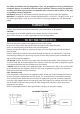
CDi BOILER: Connect the leads to the room/frost thermostat connection, after removing the link,
at the left-hand side of the control panel (see diagram). Check that the leads are properly engaged
in the connector block and that no loose wires are showing.
i BOILER: Connect the leads to the clock connection, after removing the link, at the left-hand side
of the control panel (see diagram). Check that the leads are properly engaged in the connector
block and that no loose wires are showing.
Note: CDi Boilers only.
If the timeswitch is being fitted to an appliance which already has a room thermostat fitted to it
then the thermostat connections must be altered. The unswitched live to the room thermostat
must be moved from connection Ls to ST8 with the timeswitch grey lead. (See Wiring Diagram).
Using the P-clip supplied secure the lead to the facia (the P-clip can be screwed to the facia using
one of the holes in the facia for securing the cable clamp which would be used if an external
programmer was fitted).
Refit the control panel and the lower panel before switching on the power supply.
TIMESWITCH
TO FIT THE TIMESWITCH
CDi WIRING DIAGRAMS