R PA 60/2 User Manual / Manual de Usuario Rev. 13.05.
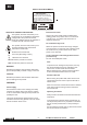
EN SAFETY RELATED SYMBOLS WARNING: TO REDUCE THE RISK OF FIRE OR ELECTRIC SHOCK, DO NOT EXPOSE TO RAIN OR HUMIDITY. DO NOT REMOVE COVER. THIS PRODUCT IS NOT INTENDED FOR USE OTHER THAN STATED. GRAPHICAL SYMBOLS EXPLANATION This symbol, wherever used,alerts you to the presence of un-isulated and dangerous voltages within the product enclosure. These are voltages that may be sufficient to constitute the risk of electric shock.
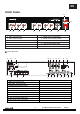
EN FRONT PANEL 11 R 12 1 1. 2. 3. 4. 5. 6. 4 3 2 5 Mic1 Input (XLR 3P) Mic1 Volume Control Mic2 Volume Control Input 3 Volume Control AUX1 Volume Control AUX2 Volume Control 6 8 7 7. 8. 9. 10. 11. 9 10 Master Tone Control (Bass) Master Tone Control (Treble) Master Volume Control Power On / Off switch Output level indicator LED 12. Power On / Off Indicator LED REAR PANEL 12 13 1 14 15 16 2 3 4 5 17 18 6 19 7 20 8 9 21 10 12. AC fuse holder 13.
EN INSTALLATION NOTES At all times, the amplifier has to be operated under appropriate conditions. This includes that the operation location provides sufficient ventilation and the device is not exposed to direct sunlight or direct radiation or reflection from any heat source. When installing the loudspeaker systems choose a location that is not affected by extreme or constant vibration or other mechanical oscillation.
EN CONNECTIONS Mains Connection (14) The supply transformer has been designed for use on either 115V AC or 230 V AC, selected by this slide switch on the rear panel (13). The amplifier is factory set at 230 V AC mains voltage. Battery Connection (24V DC) (2) When using externaI batteries, the amplifier must be earthed via the screw terminal due to the high voltages present. This is necessary to ensure the case is earthed and ensure electrical stability.
EN Aux Connection PA 60/2 provides two auxiliary inputs (18) & (19) which may be used for connecting other signal sources such as a Radio Tuner, CD or Cassette player (LINE level). Turn the front potentiometers (5) & (6) clockwise to increase the volume or anticlockwise to reduce the volume.
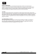
EN 4A 0 70V 0 70V 0 70V Connecting multiple speakers in parallel to the 70V output 4A 0 100V 0 100V 0 100V Connecting multiple speakers in parallel to the 100V output Telephone/Emergency (20) The Telephone/Emergency input is for emergency announcements/signals and is not affected by the Master volume control. The volume can be set by the tel. paging volume control (21). The terminals allow connection of a telephone/paging system interface.
EN TECHNICAL SPECIFICATIONS Output Power (RMS) 60 W Output Power (Peak) 90 W Audio Inputs 3 MIC, 1 LINE, 2 AUX level INPUTS MIC (Impedance/Sensitivity) 250 Ω / 1mV LINE (Impedance/Sensitivity) 47 k Ω / 200 mV AUX (Impedance/Sensitivity) 47k Ω / 200 mV Power In (Impedance/Sensitivity) 47 k Ω / 1V OUTPUTS Low Impedance 8Ω High Impedance Line 25 / 70 / 100 V Tape 4k7 Ω / 350 mV Pre‐out Frequency Response 600 Ω / 1 V 50 Hz ‐ 20 kHz +/‐ 3dB EQ Control (Bass) +/- 10 dB / 31 Hz ‐ 180 Hz /Ce
ES SIMBOLOS RELATIVOS A LA SEGURIDAD WARNING: TO REDUCE THE RISK OF FIRE OR ELECTRIC SHOCK, DO NOT EXPOSE TO RAIN OR HUMIDITY.DO NOT REMOVE COVER. THIS PRODUCT IS NOT INTENDED FOR USE OTHER THAN STATED. EXPLICACION DE LOS SIMBOLOS GRAFICOS Este símbolo, cuando aparece, le alerta de la presencia de un voltaje peligroso y no aislado dentro del producto. este voltaje puede ser suficiente para constituir un riesgo de descarga eléctrica.
ES PANEL FRONTAL 11 R 12 1 1. 2. 3. 4. 5. 6. 4 3 2 5 6 Entrada Mic1 (XLR 3P) Control de volumen Mic1 Control de volumen Mic2 Control de volumen Entrada 3 Control de volumen AUX1 Control de volumen AUX2 8 7 7. 8. 9. 10. 11. 9 10 Control de tonos (Bass) Control de tonos (Treble) Control de volumen Master Interruptor encendido/apagado Indicador LED de nivel de salida 12. Indicador LED de encendido/apagado PANEL TRASERO 12 13 1 14 15 16 2 3 4 1. Tornillos conexión a tierra 2.
ES NOTAS DE INSTALACIÓN En todo momento, el amplificador tiene que ser manejado bajo condiciones apropiadas. Esto incluye que la ubicación proporcione una ventilación suficiente y el aparato no esté expuesto a la luz solar directa, radiación o reflexión a partir de cualquier fuente de calor. Al instalar un sistema de altavoces debe elegir una ubicación que no se vea afectada por las vibraciones extremas y / o constante o de la oscilación mecánica.
ES CONEXIONES Conexión de alimentación (14) El transformador de alimentación se ha diseñado para su uso a 115V AC o 230 V AC, seleccionados por el interruptor del panel trasero (13). El amplificador está ajustado de fábrica a 230 V AC de alimentación. Conexión de la batería (24 V DC) (2) Cuando utilice baterías externas, el amplificador debe estar conectado a tierra a través del terminal debido a la alta tensiones presentes. Esto es necesario para garantizar y asegurar la estabilidad eléctrica.
ES Conexión Aux PA 60/2 proporciona dos entradas auxiliares (18) y (19) que se pueden usar para la conexión de otras fuentes de señal tales como un sintonizador de radio, reproductor de CD o Cassette (nivel de línea). Gire los potenciómetros frontales (5) y (6) en sentido horario para aumentar el volumen o hacia la izquierda para reducirlo.
ES 4A 0 70V 0 70V 0 70V Conectando múltiples altavoces en paralelo a la salida de 70V 4A 0 100V 0 100V 0 100V Conectando múltiples altavoces en paralelo a la salida de 100V Tel. /Emer (20) La entrada tel. / emer. es para anuncios de emergencia / señales y no se ve afectado por el control de volumen master. El volumen puede ser ajustado por el controlo tel. paging (21). Los terminales permiten la conexión de una interfaz de sistema de teléfono / paginación. NOTA: La entrada Tel. /Emer.
ES ESPECIFICACIONES TECNICAS Potencia de Salida(RMS) 60 W Potencia de Salida(Peak) 90 W Entradas de Audio 3 MIC, 1 LINE, 2 AUX ENTRADAS MIC(Impedancia/Sensibilidad) 250Ω/ 1mV LINE(Impedancia/Sensibilidad) 47 kΩ/ 200 mV AUX(Impedancia/Sensibilidad) PowerIn(Imped.
EQUIPSON, S.A. Avda. El Saler, 14 - Pol. Ind. L´Alteró,46460 - Silla (Valencia) Spain Tel. +34 96 121 63 01 Fax + 34 96 120 02 42 www.work.es support@work.