Sierra™ Assembly Instructions for 2 and 3-leg Workcenters #1500120 - Rev F
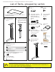
Sierra Series Workcenters - Assembly Instructions for 2 and 3-leg Tables List of Parts, grouped by carton A G Top (size and shape differ for each model) Qty: 1 Control Box Qty: 1 H #8 x ⅝"Mounting Screws Qty: 2 J #12 x ¾" Phillips head Screws Qty: 20 3 M 2 M 1 M I For assembly of two-piece tops, please refer to separate instructions.
Sierra Series Workcenters - Assembly Instructions for 2 and 3-leg Tables 1 Verify that you have all the hardware and tools needed for the assembly Check your cartons against the list on page 2 to verify that you have all the parts needed.
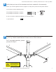
Sierra Series Workcenters - Assembly Instructions for 2 and 3-leg Tables 3 Attach Crossbars to Side Legs using ¼-20 x ⅝" Button head Machine Screws B B 3-Leg Tables D E E D F To avoid stripping the threads, always insert and make the first few turns of the screw BY HAND with an Allen wrench, ensuring it is in straight.
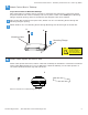
Sierra Series Workcenters - Assembly Instructions for 2 and 3-leg Tables 5 Attach Control Box to Tabletop If you do not have a Workrite tabletop: Place Control Box in position and use a pencil to mark pilot hole placement. Control box should be placed towards rear center of tabletop. Be sure to place a mark in the small part of Mounting Flange’s keyhole opening. Remove Control Box and drill pilot holes where marked.
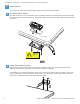
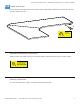
Sierra Series Workcenters - Assembly Instructions for 2 and 3-leg Tables 7 Attach Switch If you have an under worksurface switch, please proceed to Step 9b below. a On Worksurface Switch Tilt table so that you can access both sides of tabletop. Attach on worksurface switch by inserting the switch into the recessed opening. Attach back plate with screws provided with switch. Proceed to Step 10. I a Top side of table I Thread cable through this slot.
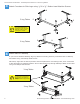
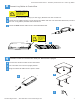
Sierra Series Workcenters - Assembly Instructions for 2 and 3-leg Tables 8 Connect Leg Cables to Control Box Never connect or remove leg or switch cables to or from control box when power is connected! Doing so will damage control box. a b If provided, use extension cable(s) for the leg(s) farthest from the control box. c Insert the blue switch cable into the terminal labeled HS. Insert the leg cables into the 6-inch control box cables and then into terminals labeled M1, M2 and M3.
r Sierra Series Workcenters - Assembly Instructions for 2 and 3-leg Tables 10 Initialize Legs After all legs and the switch are connected, and the power cord has been plugged in, hold the down arrow on the switch until the legs will make a short motion down and then back up. This initializes and synchronizes the table legs. You must complete this initialization step or your table will NOT function properly. + Hold down until table moves slightly upwards.
Sierra Series Workcenters - Assembly Instructions for 2 and 3-leg Tables 13 Install User Guide Peel off backing and place User Guide sleeve under worksurface, adjacent to switch. Be sure that the open edge faces out. N Open edge must face out. Important disassembly instructions Always remove the power from the control box before disconnecting any leg or switch cables.
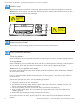
Sierra Series Workcenters - Assembly Instructions for 2 and 3-leg Tables Replacement Part Numbers Feet: 6400341-01: 6400341-02: 6400339-01: 6400339-02: 6400337-01: 6400337-02: Sierra Sierra Sierra Sierra Sierra Sierra Foot, Foot, Foot, Foot, Foot, Foot, Short (5⅜"), Sierra Silver Short (5⅜"), Charcoal Medium (7⅞"), Sierra Silver Medium (7⅞"), Charcoal Long (14¾"), Sierra Silver Long (14¾"), Charcoal Legs: 6400385-01: Sierra End Leg - Sierra Silver 6400385-02: Sierra End Leg – Charcoal 6400386-01: Sierr
r r Sierra Series Workcenters - Assembly Instructions for 2 and 3-leg Tables Sierra Series Workcenters Special Settings 55 5 60 50 10 45 15 40 20 35 1 30 25 Initialize legs if you have not done so already After all the legs and the switch are connected and the power cord has been plugged in, hold the down arrow on the switch until the legs make a short motion down and then back up. This initializes and synchronizes the table legs.
r 55 Sierra Series Workcenters - Assembly Instructions for 2 and 3-leg Tables 3 a b c d e 60 5 50 10 45 15 40 Adjust Starting Digital Height Readout 20 35 30 25 (Use if you have a worksurface that is not 1⅛" thick, causing inaccurate readout of the lowest height) Lower the table to the lowest position and measure the height from the floor to the top of the worksurface. (not shown) Press the “SET” button with a ballpoint pen (Do NOT use a paperclip - it may damage the electronics).