
Owner`s manual


2012 World Cat 270TE Owners Manual
Chapter 10: 270TE OPERATION AND SCHEMATICS
10.1 OPERATION OF STANDARD EQUIPMENT
10.1.1 Battery
Layout and Management
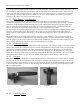
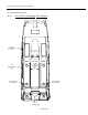
The 270TE is equipped with three batteries located under the helm seat. They can be reached using the access hatch
located on the aft wall of the leanbar. A cranking battery is installed on each side, and a dedicated house battery is
installed along the centerline of the boat. Wire leads are connected to the battery management panel located on the
forward wall of the leanbar. (See section 6.5 thru 6.5.4 for information regarding the operation of this panel.) The
cranking leads and egine negative leads run aft, through the hull rigging tubes, from the leanbar to a positive stud and
negative stud mounted on the bulkhead in each aft rigging compartment. The engine leads are connected to the
battery system using these studs (see diagram below).
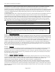
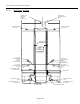
The house battery provides the power for all your DC accessories. The main lead connects to the “HOUSE” switch on
the battery management panel. From there current is routed to the console through the 50 amp “DC Main” breaker
located on the top left corner of the battery management panel. During normal operation this breaker can remain in
the “ON” position, and the “HOUSE” switch can be used to control the flow of current. The main ground for all DC
accessories is tied into the common ground on all batteries (see diagram below).
For a detailed drawing of the battery management panel connections, see the diagram in section 10.4.5 in this
chapter.
10.1.2 Digital Control System
Page 10-52