
Instructions / Assembly

4
c. Relier le fil vert (ou le fil nu en cuivre) au fil de mise à la terre du circuit
d’alimentation.
d. Utiliser des capuchons de connexion homologués UL qui conviennent aux format,
type et nombre de conducteurs. Aucun brin ni fil ne doit être desserré.
e. Sécuriser les capuchons de connexion au moyen de ruban isolant homologué U.L.
f. Replier délicatement les fils raccordés à l’intérieur de la boîte de sortie.
7. Attach the canopy onto the mounting bracket and tighten the canopy screw on to the
mounting bracket to secure the fixture.
8. Installez l'ampoule électrique (la bombilla se vende por separado).
9. Adjust the length of the bottom hex nut on the threaded tube, then ordinal place the
steel washer, plastic washer, diffuser and plastic washer, steel washer on to the
threaded tube, and tighten with the hex nut.
10. Place the bottom cap on to the threaded tube and tighten with the decorative cap.
REMPLACER LA (LES) AMPOULE(S)
1. Couper l’alimentation électrique du plafonnier.
2. Loosen the decorative cap, and remove the bottom cap, then loosen the hex nut and
remove the steel washers, plastic washers and diffuser.
3. Retirer l’(les) ancienne(s) ampoule(s) et installer la (les) nouvelle(s) ampoule(s).
4. Replace the steel washers, plastic washers, diffuser and tighten with the hex nut,
then replace the bottom cap and tighten with the decorative cap.
5. Remettre le plafonnier sous tension.
ATTENTION: Consulter l’étiquette de remplacement de l’ampoule située sur
l’appareil. Ne pas dépasser la puissance recommandée.
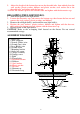
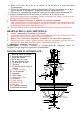
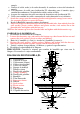
DIAGRAMME D’ASSEMBLAGE :
1. Boîte de sortie de courant
2. Capuchon de connexion
3. Fil neutre (Blanc)
4. Fil de mise à la terre
5. Fil sous tension (Noir)
6. Vis de mise à la terre
7. Traverse
8. Vis de la boîte de sortie de
courant
9. Canopy assembly
10. Vis de monture
11. Ampoule
12. Tige filetée
13. Decorative frame
14. Diffuseur
15. Steel washer
16. Plastic washer
17. Hex nut
18. Capuchon inférieur
19. Bouchon décoratif
13
5
18
19
17
15
16
14
12
11
10
9
8
6
7
4
3
2
1