This equipment has been tested and found to comply with the limits for a Class A digital device, pursuant to Part 15 of the FCC Rules. These limits are designed to provide reasonable protection against harmful interference in a residential installation. This equipment generates, uses and can radiate radio frequency energy and, if not installed and used in accordance with the instructions, may cause harmful interference to radio communications.
Introduction The 7001 RF Terminal is a low cost, easy-to-use radio frequency interactive terminal which communicates with PCs (or any computer) by RS-232 serial port or USB. This new terminal offers unprecedented power and ease of use, while maintaining compatibility with programs written for the older Worth Data Terminals. The list of fantastic features include: Low Cost Up to 2.
While the new 7001 series RF Terminals are fully software compatible with the older 70 and 700 series terminals, there are a few differences between them. The differences between this new generation of Worth Data RF Terminals and the generation referred to within this manual are: 1. 64 Terminals per Base Station instead of 16. Valid Terminal IDs are 0-9,A-Z,a-z, and – =. 2. Valid Channels are 0-5. 3.
Table of Contents Chapter 1 Installation ............................................................. 1-1 Components ............................................................. 1-1 Installation Sequence ............................................... 1-1 Connecting the Base Station to a serial port ............ 1-2 R/F Terminal Operation........................................... 1-4 Installing the R/F Terminal Utilities Software......... 1-8 Chapter 2 RF System Setup .................................
Appendix D Firmware Upgrades .............................................. D-1 Appendix E Code 39 Specifications ........................................ E-1 Appendix F Code 93 Specifications ........................................ F-1 Appendix G Codabar Specifications ....................................... G-1 Appendix H Code 128 Specifications ...................................... H-1 Appendix I Interleaved 2 of 5 Code Specifications ................
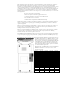
Chapter 1 Installation Components The components in your R/F Terminal system will vary according to the configuration of your system. Your R/F Terminal shipment should contain at least: An R/F Terminal T7001 or LT7001 (unit includes keypad and display). If the R/F Terminal is an LT7001 model, it will have an integrated laser scanner built-in to the body of the terminal. Each terminal is shipped with a shoulder strap, boot, and Setup Menu.
to Start Menu, Settings, System, Device Manager, Ports (COM and LPT). Now run one of the RF Terminal demo programs found on the Utilities CD-ROM. 5. If using the USB port, you will be prompted to load a driver when the Base is pugged into the computer for the first time. The driver is located on the Utility CD in the directory “Base USB Driver”. 6. Now run one of the demo programs to validate that everything is working. If you have problems, refer to the Trouble Shooting Section.
Base station. If the extension cable appears to be the culprit, check to be sure that Transmit lines are connected to Receive lines. USB Driver Installation A virtual COM port (VCP) driver is available for Linux, Mac OSX, Windows 2000, XP, 2003 Server and Vista. All 3 versions are supplied on the Utility CD and the latest version can be downloaded from: https://www.silabs.com/products/mcu/Pages/USBtoUARTBridgeVCPDrive rs.aspx Install the driver before plugging the Base into the Host Computer.
R/F Terminal Operation Using the RF Terminal keypad… The R/F Terminal is turned on by pressing the green ON/OFF button located in the upper left-hand corner of the R/F Terminal keypad. The R/F Terminal has a Shut Down Time feature that allows you to determine the length of time the R/F Terminal must be inactive before automatically shutting down to conserve battery power. When the R/F Terminal shuts down, simply press the ON/OFF button to resume operation.
mm/dd/yy hh:mm BATÓÓÓÓÓÓÓÓÓÓÓ-zz% zz=percent in numbers i.e. 99, 10, 05 Press the STATUS key again to resume processing. To change the internal battery: 1. 2. 3. 4. 5. Turn OFF the R/F Terminal. Remove the battery holder door on the back of the R/F Terminal by removing the two screws holding the door in place.. Remove the old battery and insert a new one, making sure to orient the battery with the battery contacts facing the battery connector..
R/F TERMINAL 3C1nnnx TERM ID: 0 R:nn USA CHANNEL: 0 6/6 HIT ANY KEY (The opening screen can be bypassed upon power up. See Chapter 2) The first line on the screen, R/F TERMINAL 3C1nnnx, gives the firmware revision number. TERM ID: 0 refers to the current Terminal ID. The default setting is 0. Every Terminal must have a unique ID. R:nn refers to the version of the radio processor firmware. Line 3 refers to the channel currently used by the R/F Terminal. USA CHANNEL: 0 refers to a Terminal set to channel 0.
SITE TESTING KEY [YES/NO]?_ Press YES to enter SITE TESTING. SITE TESTING is an excellent way to assess your R/F communication in any area. It can help you determine the best place to locate your Base station for maximum R/F performance as well as troubleshoot problems that may relate to range or interference. Press NO to loop back to the SIGN ON? prompt. You can back-out of any mode or prompt by pressing the F1 key.
To install any of the programs found on the Utilities CD, simply insert the CD into your CDROM drive. The install program should start automatically. If it does not, simply run the SETUP.EXE program found on the CD. Running the demo programs… The demo programs are all programs provided to help you test your R/F Terminal with a two-way communication program.
Chapter 2 RF System Setup RF Terminal Setup The RF Terminal itself can be configured using the Terminal keypad or by using the bar coded Setup Menu. Even if you configure the RF Terminal using the keypad, you may need the bar coded Setup Menu to use as a reference. Most users do not need to change anything in the setup. The most commonly changed setup parameters are the Terminal ID (especially if you have more than 1 terminal) and the Channel (if you are adding an additional Base station).
Default RF Terminal Configuration Parameter Default Setting Radio Terminal ID 0 Parameter RF Channel 0 check digit not transmitted Code 39 Enabled Plessey Code disabled MSI Code Accumulate Mode ON Default Setting Disabled Label Code5 disabled stop/start chs not xmit Code 128 check digit disabled Enabled EAN/UCC 128 disabled Caps lock OFF 2 of 5 Code Code 11 Disabled Disabled RSS-14 Disabled I 2 of 5 Code disabled Code 93 Disabled 6 digit code length UPC/ EAN Codabar Full ASCII
More than one Setup Parameter can be changed before you scan END SETUP. For example, if you scanned START SETUP, then “Beep Tone”, then 3, then “Speaker Operation”, then 1, then END SETUP, this would change the beep tone to “high”, and turn the speaker "off". If you are using a Laser Scanner to setup the RF Terminal, the beam will often cover more than one bar code. Cover any adjacent bar codes before scanning, and then check the RF Terminal display to make sure the correct setting was entered.
The groups in the keypad Setup Menu contain the following setup parameters: Setup Group Parameter Setup Group RF Setup 0 RF Terminal ID RF Channel Security Code Skip opening screens Date/Time 3 Set Time Set Date Date Format Display of Year Code 3 of 9 UPC/EAN Code 2 of 5/I 2 of 5 2 of 5 Length Code 128 Codabar MSI/ Plessey Code 11 Code 93 RSS-14 Battery 4 Recharging or Not Bar Codes 1 Speaker 5 Speaker Volume Headphone Volume Beep Tone Other 6 Shut Down Time Preamble Postamble Voice Messages L
RF Terminal Setup Parameters Default settings are shown in bold type in this manual and are marked by a * on the bar code Setup Menu. The RF Terminal will typically require no setup changes except, Terminal ID (if more than one terminal) and enabling bar codes to be read other than UPC or Code 39. Battery RF Terminal ID Default ID Available ID's 0 0-9, A-Z, a-z, - = Every terminal needs a unique Terminal ID. The default Terminal ID is always shipped as 0.
Security Code Disabled Enabled 0 1 A Security Code can be utilized to minimize the possibility of a Base Station listening to data from a Terminal that is talking to a different Base Station. A Security Code can also prevent interference from having many Base Station/RF Terminal configurations in one area; i.e. a merchandise mart with multiple vendors all running RF Terminal networks. A Security Code consists of 3 characters - any combination of ASCII 33 - ASCII 126.
the first key pressed in a data entry sequence. If it is not the first data entered, the arrow key is ignored.
your batteries and you can expect shorter battery life. The default setting is 30 seconds. RF Setup Skip Opening Screens No Go to Two-Way (SIGN ON) Go to One-Way (ONE WAY) 0 1 2 Many users want to skip the opening screens and go directly to SIGN ON or ONE WAY communication once their programs are fully operational. Selecting 1 or 2 will automatically take the operator to the corresponding mode and into your application, skipping the usual Mode Menu (SIGN ON?Y/N, SETUP?Y/N, ONE WAY?Y/N, SITE TESTING?Y/N).
Speaker and Headphone Volume Controls Speaker By selecting Speaker in the keyboard Setup Mode, you get to the options to control the Speaker/Beeper and Headphone volumes. If you are using headphones, you will want set the Speaker volume to 0 to conserve batteries. Volume settings possible are 0-9.
Bar Codes Code 3 of 9 (Code 39) Enable Code 3 of 9 Disable Code 3 of 9 Enable Full ASCII Code 39 Disable Full ASCII Code 39 Enable Code 39 Accumulate Mode Disable Code 39 Accumulate Mode Enable Start/Stop character transmission Disable Start/Stop character transmission Enable Mod 43 Check Digit Disable Mod43 Check Digit Enable Check Digit transmission Disable Check Digit transmission Caps Lock ON Caps Lock OFF 0 1 2 3 4 5 6 7 8 9 A B C D The Start and Stop character for Code 39 is the * character.
Bar Codes UPC/EAN Enable UPC/EAN Disable UPC/EAN Enable UPC/EAN Supplements Disable UPC/EAN Supplements Enable transmission of UPC-A NSC or EAN 13 1st 2 digits Disable transmission of UPC-A NSC or EAN-13 1st 2 digits Enable transmission of UPC-A and EAN-13 check digit Disable transmission of UPC-A and EAN-13 check digit Enable transmission of UPC-E NSC and EAN-8 1st digit Disable transmission of UPC-E and EAN-8 1st digit Enable transmission of UPC-E and EAN-8 Check digit Disable transmission of UPC-E and E
parameter. To enable UPC-E1 reading, set the 2 of 5 Code parameter to 8. To turn off UPC-E1 reading, set it back to the default of 9. If you prefer to transmit UPC-E bar codes in a 6-digit format while EAN8 is transmitted in its original 8-digit format use setting F. This will allow you to use settings 9 and A and still transmit EAN-8 as 8 digits. UPC-A can be transmitted in EAN-13 format by adding a leading 0 (USA county code) to the UPC-A data. This setting is found in the Laser Options parameter.
Bar Codes Codabar Enable Codabar Disable Codabar Enable CLSI Codabar Disable CLSI Codabar Disable Start/Stop character transmission Enable Start/Stop character transmission 0 1 2 3 4 5 CLSI is a form of Codabar often used by libraries. Setting 5 will transmit the Codabar start and stop characters with the bar code data to your computer. If you are varying the start and stop characters to differentiate between different labels, transmitting the start and stop can be helpful.
2 of 5 Length Default setting Valid entries To read variable length 2 of 5 codes 06 00-98 00 2 of 5 is so susceptible to misreads that the RF Terminal adds an additional safeguard - it can be configured to look for fixed-length data only. The default setting of 06 causes the RF Terminal to read only 2 of 5 codes that are 6 digits in length. To set the RF Terminal to read a different length, scan any two-digit number from the bar pad table.
14 digits + UCC-128 format, i.e. ]C110012345678902 3 By default, standard RSS-14 is disabled, scan 1 to enable. We support the standard and stacked versions of RSS-14 formats. For more information on RSS-14, see the AIM website at http://www.aimglobal.org/standards/symbinfo/rss_overview.asp Bar Codes Code 93 Enable Code 93 Disable Code 93 Enable Full ASCII Code 93 Disable Full ASCII Code 93 0 1 2 3 Code 93 is similar in character set to Code 39. See Appendix F; Code 93 for more information.
trimming. Preambles trim characters from the front of the data. Here are some examples: Data Preamble 123 12345678 12345678 12345678901 123456 Data Transmitted XYZ ~3XYZ ~9 ~A ~5 Preamble trims leading characters XYZ123 XYZ45678 12345678 1 6 Using the Bar Code ID feature and the Preamble, you can trim data selectively, trimming characters only on the bar code type specified.
4. To clear the Postamble and return to the default (no Postambles defined), scan CLEAR at step #2, and then continue with your setup. You can use the Postamble to trim characters from the data you are entering into the RF Terminal. You can trim from 1-15 characters from the data by creating a Postamble of: ~x where ~ is ASCII 126 and x is a single hex digit 1-F (corresponding to 1-15). Data that is shorter than the trim amount is transmitted without trimming.
characters, with the RF Terminal outputting hex 92 every time it sees hex 31. To re-assign characters: Scan Characters Scan up to seven 4-digit pairings where the first 2 digits represent the hex number to replace and the second 2 digits represent the hex number to insert. You can have up to seven character reassignments. Scan SET You can eliminate the output of a character by using FF as the hex number to insert. For example, if you wanted to eliminate all $, following the above instructions, enter 24FF.
Set Time The time is set using a 4-digit military hhmm format. For example, to set the time to 3:08 p.m., you would enter 1508. The time can be scanned in from the bar coded Setup Menu or entered from the RF Terminal keypad. To display the time during operation, press the STATUS key. Display of Year 2 digit 4 digit 0 1 By default, the RF Terminal is configured to display and transmit the year in a 2-digit format; i.e. 1999 would transmit and display as 99.
to keep reading until it gets two results that are identical. This "double scan checking" takes longer but will minimize misreads since it must get the same result twice before considering it a "good" read. 4-second laser beam increases the amount of time the laser beam is activated, giving the laser more time to try and read a code. This option is useful for trying to read poor quality code.
Data Bits RS232 7 bits 8 bits 0 1 RS232 Stop Bits 1 bit 2 bits 0 1 RS232 Protocol None XON/XOFF Maintain backward compatibility for illegal statement handling Illegal statement handling for current versions 0 1 E F Settings 0 and 1 pertain to use of a serial Printer with your RF Terminal. Use setting 1 for XON / XOFF if your serial Printer supports it. It DOES NOT apply to the Cameo and QL3 Printers.
If you know which COM port you are attached to, select that port in the program, then click "Continue". If you are unsure of the COM port number, the program can find it for you. Enter the range of COM ports to search, then click "Find Base Station". The program will look for the Base and determine its current configuration. Once the program finds it, it will display the RF Channel (default is 01) and the Firmware Version (xxxxx-pp).
Once you have made any and all changes, click on the "Send Settings" button. Your Base is now configured! Testing the RF link between base station and host Use the following command to test the transmission of data from host to Base and back again to the host: @@*Edataaaaaaaa where dataaaaaaaa is any string of data, terminated by EOT. This string should be sent from the host to the Base Station.
Chapter 3 Operational Theory Before you jump in and start writing a complex host program, it might be nice to be familiar with the theory behind the operation of your RF Terminal. The RF Terminal has three different modes of communication: Two-Way Mode - the host program transmits requests for data to the terminal via the Base Station. The RF Terminal transmits a response back to the Base Station, which in turn sends the data on to the host program.
A little more in depth… This RF system’s dialogue is Terminal initiated. The Terminal says, “I’m here, give me something to do. The Worth Data RF system is different from other systems in that our RF Terminal does not constantly “listen” for a data prompt from the host. We decided to use a different approach that would help to eliminate unnecessary radio traffic, conserve battery power, reduce the size of the Terminal, and greatly simplify the operation.
the terminal goes to sleep until the time it took the last time for the host to respond has expired; then the terminal wakes up and listens. If it has nothing, it retransmits its data and waits for a response. The original data transmission could have collided with another message, or the Base could have received the Terminal's data but had not yet received the host's prompt response.
How the One-Way RF System works The RF System can be used to perform “dumb” data entry to the computer – you could even use Portkey to transmit the data through a serial connected Base as though it has been entered from the keyboard. This is useful if you want to enter data directly into an application. This type of data transmission is called One-Way Mode.
receives the data, the RF Terminal displays the following prompt: Data Received Was aaaaaaaaaaaaaaaaaa Enter Data? Where aaaaaaaaaaaaaaaaaa is the data received by the Base Station (and transmitted to the Host Computer if connected). You can exit One-Way Mode simply by pressing the F1 key on the RF Terminal keypad. In One-Way Mode, the RF Terminal transmits its Terminal ID to the Base Station but it does not pass it on to the Host Computer.
Chapter 4 Performance Issues Evaluating your area of planned operation Since every operational environment is different, it is impossible for us to tell you exactly what equipment you need and where you should put it to achieve maximum performance from your RF System. However with 2.5 miles of open area range, unless you are going through a lot of walls, you probably won't care where the Base is located.
the Base Station on the ceiling with the antenna pointing down is the best. Performing a Site Test As we have said before, the Site Test is your most valuable tool for evaluating your planned area of operation. All you need to perform a Site Test is a RF Terminal, a Base Station and it's 5v power supply. There are a few things you need to do though before you begin: Make sure all other Base Stations are turned OFF. Make sure that the Base Station and RF Terminal you are using are set to the same channel.
The first line shows the percent of successful transmissions. As long as you are getting at least 90%, you will have excellent results in the location tested. If you don’t get the minimum results shown above: 1. Try hanging the Base Station upside down or tilted toward the area of usage – this alone can double the effective range. 2. If using a European terminal, try a different channel. You may find less interference on another channel. There are several to choose from, only try 1 or 2 others.
Chapter 5 Before you begin programming… The RF Terminal operates in two basic ways: One-Way communication, where all data transfer is initiated by the RF Terminal. This is not very useful, because it has no editing or prompting. The Base Station itself simply acknowledges the receipt of the data by echoing it back to the Terminal.
Look for All Errors. Be sure your program is trapping all possible error conditions that the Base Station may return to you. The list includes: Sequence Errors detected Illegal Command detected Base Station Initialized Addressing a Terminal Not Signed In Command without an ID All of these error conditions are detailed in the next chapter. Don’t forget to program for them; this is a common mistake. Failure to trap them will give create very strange, unpredictable results.
Keep in mind that if a Terminal has SIGNED OUT in midtransaction, the Base Station clears any pending message for that Terminal before it will allow it to SIGN ON again. Make allowances to re-send messages or prompts that were cleared upon SIGN ON if necessary. If a Base Station has a hardware failure, neither the Terminal nor the host computer will be able to communicate with it.
Chapter 5 Programming for the RF Terminal The four levels of programming support offered for the RF Terminal are: 1) Low Level ASCII sequences sent to and from the Base Station by the user program reading/writing to the serial port. 2) Low Level ASCII sequences sent to and from the Base Station using DLL for Windows for serial port reading/writing. 3) Active X drop-in components. Every necessary function is defined. You just complete the code for each function.
The Command(s) section of the message always starts with the second byte and can consist of one or more commands - including data to be displayed or voice messages to be broadcast. The last byte is always ASCII 4 (EOT) to terminate the message.
These are valid entries for the third position character: 0 1 2 3 4 5 A B C D E S p P R K M No data input for this Command, Display ONLY Data input required from the keypad or scanner Only keypad input allowed, start un-shifted Only keypad input allowed, start SHIFTED Only scanner input allowed Only accept YES (Enter key or C key) or NO (0 key or B key) keypad response. (Terminal sends 1 for YES, 0 for NO). C and B key are there to facilitate YES/NO keypad entry while scanning with integrated laser.
Messages can be a combination of multiple commands, (i.e. voice messages, initialization, clearing lines, requesting data entry), up to 231 characters in length. A message cannot though, contain an @S command in combination with any other command. A message also should not contain more than 1 request for data entry (third character in command is 1). For example: @1,1,1,ITEM@2,1,1,QTY has two data entry “prompt” commands combined.
There is no reply to the host except the magstripe data. If the card cannot be read, pressing the ENTER key on the Terminal will send back ID+CR. This is the breakout method. This command must be the last in a series of commands. For example, the following would be a typical multi-command statement: @C0@1,1,0,Swipe Card@M! U1 MCR 80 T2 (CR)(LF)(EOT) where CR is ASCII 13 LF is ASCII 10 EOT is ASCII4 The statement causes the RF Terminal to transmit the string "!U1 MCR 80 T2 CR LF" to the Cameo printer.
The following table shows the programming differences for 4 lines/6 lines: Command @C0 4 Line Command did not exist @C5 Cleared all lines on a 4 line display Command did not exist @C6 6 Line Clears all lines on both a 4 line display and a 6 line display. Clears line 5 on a 6 line display. Clears ALL lines on a 4 line display. Clears line 6 on a 6 line display.
Here are some sample command statements utilizing some of the programming tips offered above: @2,1,1,ENTER ITEM NO @V23@1,2,1,WRONG ITEM @C1@1,7,0,PICKING @1,1,1,ITEM@2,1,1,QTY Display ENTER ITEM NO on line 2, position 1 and wait for wait for data input. This is a valid single command statement – it ends with a data entry request. Play voice message 23, display WRONG ITEM on line1, position 2 and wait for data input. This is a valid multiple command statement – it ends with a data entry request.
Serial Reply After a Serial command (@S) has been successfully completed, the Base Station sends to the Host the Terminal ID followed by a CR. Serial commands are typically used for attached serial printers. Serial commands cannot be combined with other commands in a message to the Base Station/Terminal. Remember, you can only send 231 characters (including the ID + @S + EOT). SIGN ON To login to the host computer, the user presses a key on the RF Terminal at power-up to get to the SIGN ON screen.
then send a message periodically to re-assure the operator (remember to ask him to press ENTER) that instruction is coming or tell him to see his supervisor for re-assignment (or whatever makes sense for your application). Ideally, if the operator is leaving the area (to go to lunch or move to another building) before he is out of range of the network, he should SIGN OUT, then SIGN ON upon his return.
Base Shut Down Due to Host Logic Error Check your program for the sequence error before starting again. The host program will have to reinitialize the Base Station or you will have to cycle power on the Base Station and have the Terminal Sign On again in order to continue. Sequence Error Message The host program must observe the one-for-one "host prompt/terminal response" protocol at all times. The host cannot send a second data entry prompt until it has received a response to the first data entry prompt.
2?CR If a command is sent from the host to the base station without a valid terminal ID character, such as: @1,1,1,Scan Serial Number since the command doesn’t specify which terminal it is meant for, the base sends the following message back to the host: *?CR If the Base Station receives more than 231 characters, it treats that statement as an Illegal Command.
Since ASCII 19 is XOFF, the ASCII 19 character can be changed to ASCII 20 for XON/XOFF sensitive systems by changing the Base Station Setup. See Chapter 2; RF System Setup for details. The Base Station Initialized message is provided so that the host will know that there has been a power interruption on the Base Station. When a serial device powers up, the first byte transmitted is often garbage.
The Control keys can be used without pressing the ENTER key by using the Control Keys Only Terminal Setup parameter. See Chapter 2; RF System Setup for details.
LOW Level ASCII Sequences using a DLL The DLL disk is included with every RF Terminal system. To install the program, run the INSTALL.EXE program from Windows Explorer. The program, PromptCOM comes in both 16 bit and 32 bit versions of a Windows Dynamic Link Library (DLL) that allows programmers to easily add the ability to send prompts and receive data from their RF Terminal via the RF Base Station or direct serial link.
PromptCOM/ActiveX is a drop in COM component that allow programmers to easily add the ability to send prompts to and receive data from their R/F Terminal via an RF Base Station. It is compatible with Visual Basic, Visual C++, Delphi, and most other 32-bit development platforms. See the help file for installation instructions. Programming Considerations for Serial COM Before making any method calls, make sure you : Set the COM port properties (device name, baud, parity, bits,) as desired.
2. Two (or more) terminals using the same ID (terminal ID conflict).
Concepts - Serial COM When you use drop-in components in your program you will follow the standard object-oriented programming paradigm that uses properties, methods, and events to implement the functionality of the drop-in component. Properties are the various configuration variables used by the drop-in component. An example of a property is the ComDeviceName setting. Methods are function calls used to issue commands and access features of the drop-in component.
ActiveTerminal Valid values: Definition: 0 -63 This is the terminal ID (0-63) to which method call instructions are directed. ComDeviceName Valid values: COM1-COM16 Definition: This is the serial port that this instance of the control will use. If you have more than one base station, drop in another WDterm control and set its ComDeviceName for your other COM port(s).
Quiet Valid values: True, False Definition: If Quiet is set to True then any status and error message generated by WDterm will be suppressed. Methods - Serial COM Methods are commands that you issue to the WDterm control. All of the "Inputxxx" commands cause the terminal to wait for operator input. Note that your development environment may show more available methods for the WDterm control than are listed here. This is normal. You may ignore methods you see that are not listed here.
InputKeyBd Parameters: line, position, prompt, shifted, timestamped Function: This instructs the ActiveTerminal to display the prompt at line and position and wait for data to be entered from the terminal keypad only. If shifted is set to “true”, the terminal will start in shifted mode. Timestamped appends a (hhmmss) prefix to the returned data.
data string to the host (fires the OnTermData event handler). OutputSerial Parameters: data Function: This instructs the ActiveTerminal to send data to the terminal’s serial port. Data must be less than 231 characters in length for each call to OutputSerial. SendDisplay Parameters: line, position, prompt Function: This instructs the ActiveTerminal to display the prompt at line and position. Must be followed by an "Input" method call to take effect.
PlayVoice Parameters: msgnum Function: This instructs the ActiveTerminal to play voice message number msgnum. Msgnum may be a value from 1 to 99. Must be followed by an "Input" method call to take effect. ReInit Function: This instructs the ActiveTerminal to re-initialize. Must be followed by an "Input" method call to take effect. Base Stations use the message "Buffer Reinitialized..." to indicate a single terminal reinitialization.
OnTermSignIn6 Data passed: terminal Event: A six-line terminal has signed in. Terminal ID is passed in terminal. OnTermSignIn4 Data passed: terminal Event: A four-line terminal has signed in. Terminal ID is passed in terminal. OnTermSignOut Data passed: terminal Event: A terminal has signed out. Terminal ID is passed in terminal. OnTermData Data passed: terminal, data Event: A terminal has sent data in response to an Input method call.
PromptCom/ActiveX is designed to prevent illegal commands but software is not always perfect and we may not have imagined all the ways in which our customers will want to use it! OnTermUpArrow Data passed: terminal Event: The up-arrow button has been pressed on a terminal. You must issue another Input method call before WDterm can respond to another keypress on the terminal. OnTermDownArrow Data passed: terminal Event: The down-arrow button has been pressed on a terminal.
Event: The END button has been pressed on a terminal. You must issue another Input method call before WDterm can respond to another keypress on the terminal. OnTermSearchKey Data passed: terminal Event: The SEARCH button has been pressed on a terminal. You must issue another Input method call before WDterm can respond to another keypress on the terminal.
You can link server and client through a dial-up or DSL internet link as long as the server has a static IP address and your router passes the above ports. If you are unsure of how to set up your IP configuration properly, refer to your network administrator for help. Client Utility Make sure the Client Utility is properly installed on the client computer and communicating with at least one Base Station. Test the Client by cycling power on the Base Station.
It is very important to keep track of "login status" for each terminal. Every SignOut event should have an associated SignIn event and a given terminal should not be allowed to SignIn twice without and an intervening SignOut. Multiple SignIns from one terminal without appropriate SignOuts indicate either: 1. A terminal going out of range and having its power cycled before returning within range OR 2. Two (or more) terminals using the same ID (terminal ID conflict).
Note that your development environment may show more properties for the WDIPterm control than are listed here. This is normal. You may ignore pro-perties you see listed in your development environment that are not listed here. ServerOn Valid values: True, False Function: Set to True to enable the server. Set to false to turn the server off. You should leave this off unless your program is actually running. Setting it to True at design-time can cause problems.
Function: This instructs the terminal attached to client basename on channel to display the prompt at line and position and wait for data to be entered from either terminal keypad or scanner. If shifted is set to "true", the terminal will start in shifted mode. Timestamped appends a (hhmmss) prefix to the returned data.
Function: This instructs the terminal attached to client basename on channel to display the prompt at line and position and wait for data to be entered from the terminal keypad only. The entered data is not displayed on the terminal.
InputSerial Parameters: basename, channel, terminal, line, position, prompt Function: This instructs the terminal attached to client basename on channel to display the prompt at line and position and wait for data to be received through the terminal serial port. Waiting for serial input can be bypassed by pressing the enter key on the terminal which will send an empty data string to the host (fires the OnTermData event handler).
SendDate Parameters: basename, channel, terminal, line Function: This instructs the terminal attached to client basename on channel to display date and time on the specified line number. Must be followed by an "Input" method call to take effect. Beep Parameters: basename, channel, terminal, count Function: This instructs the terminal attached to client basename on channel to beep count times. Count may be a value from 1 to 9. Must be followed by an "Input" method call to take effect.
Events - TCP/IP COM WDIPterm events occur when a specific condition is met. When an event is "fired", an event handler function in your application is called. Though the details of exactly how it is done varies from one programming environment to the next, the source code skeletons for the various event handlers are automatically generated and inserted into your source code for you. See the samples for more specific information. Each event passes relevant information to your event handler function.
Event: A terminal on channel at client basename has sent data in response to an Input method call. OnTermNotSignedIn Data passed: basename, channel, terminal Event: A command has been sent to a terminal that is not signed in. OnTermSequenceError Data passed: basename, channel, terminal Event: The one-for-one host prompt/terminal response protocol has been violated. The host cannot send a second Input command until it has received a response from the first Input command.
Data passed: basename, channel, terminal Event: The left-arrow button has been pressed on a terminal. You must issue another Input method call before WDIPterm can respond to another keypress on this terminal. OnTermRightArrow Data passed: basename, channel, terminal Event: The right-arrow button has been pressed on a terminal. You must issue another Input method call before WDIPterm can respond to another keypress on this terminal.
Portable Printers Cameo and QL 3 Common Information Both of these printers are stocked by Worth Data for the convenience of our users who need portable printing. These printers do not require any special protocol; they do not require the “wake-up byte” as do other printers. They do require a special cable that can be ordered from Worth Data (part #C12); cable pin-outs are available in Appendix C: Cable Pin-outs.
When the Terminal sends data to the host, it sends it in the following format: RF Terminal ID + DATA + CR Typically, the data is simply a string of characters, but in the instance of data coming from the magstripe reader, there are some additional characters you need to be aware of.
Each printer is shipped with a no charge roll of thermal paper that can be used for development, including determining the exact label size that best fits you needs and the capabilities of the printer. We stock the 2” and 3” QL 3 printers with several label sizes immediately available including: Part Number E2L1 E2L2 E2L3 E2L4 E3L1 E3L2 Description 2"x1" Vinyl Shelf Adhesive Labels 2"x1.25" Paper Permanent Adhesive Labels 2”x2” Paper Permanent Adhesive Labels 2”x1.
Chapter 5 Voice Message Operations The RF Terminal’s exclusive use of voice prompts allows you to overcome problems such as literacy, language and lighting. With proper planning, voice prompting can enhance your RF Terminal application, making it faster and simpler. Voice messages are recorded using a utility program included on the Utility CD-ROM and then uploaded to the RF Terminal. Playback of a voice prompt is triggered by a prompt from the host computer.
prompts or error messages will make it easier for the user to distinguish between them. Be sure to record error messages for all possible problems that the user may encounter during a session. Once the operator becomes accustomed to listening to the voice prompts, it may become easy to overlook a “display only” error message.
Enter the message number you are going to record. For this example, enter message #03 (by default this is a blank message) by pressing 03, then the ENTER key. The RF Terminal screen now shows: HIT ANY KEY TO START RECORDING To record a message, press any key and hold it down. When you release the key, immediately start speaking into the microphone. To practice, let’s record something in message #03. Get ready to say ITEM (in English or your language) into the microphone of the RF Terminal.
Terminal detects very low batteries, it will play message #31, regardless of what is recorded there. You could record “Happy Birthday” and the RF Terminal would broadcast it any time it detected the low battery condition. To avoid confusion, try to keep the error messages somewhat related to the error condition they represent.
Default Voice MessagesHere are the default messages and the numbers they are recorded under: Message Recorded Message # Prompt ITEM QUANTITY #01 #02 Error messages LOW BATTERIES CHANGE BATTERIES TRANSMISSION FAILED #31 #32 #33 Cloning Voice Messages and Setup from RF Terminal to RF Terminal If you have several RF Terminals, you can record all of your voice messages in one RF Terminal and then simply “clone” them to your other RF Terminals.
End of Cloning Hit Any Key_ If you did not hear the correct messages or you heard no messages at all, check your cables and receiver/master setup - you may have transmitted from the wrong RF Terminal. DATA XMIT ERROR CYCLE POWER If you get the DATA XMIT ERROR message, you have to restart the whole cloning procedure.
Chapter 8 Troubleshooting General Considerations Site Test The most basic tool for troubleshooting is the Site Test at 50 feet range. (See Chapter 4 for the details on how to do a Site Test). If the Site Test fails at close range (50 feet), you have found the problem. The radio on either the Base Station or the RF Terminal is defective. A Terminal may operate poorly at a distance of less than 10 feet from the Base due to high transmitter power. Make sure to Site Test at least at 50 ft. range.
If the Terminal displays the “Waiting on Host Prompt” message, the host program is not communicating with the Base Station. There is no radio problem, because the Base Station has already acknowledged the Terminal’s Sign In. The Terminal is waiting on the Host to tell it to do something. Try the demo program; if it works the problem is your program. If using the Active X program with XP, be sure "connection pooling" is disabled. If the demo program fails, the problem is one of the following: 1.
Message Meaning – Action Required This is a normal message, generated when you first establish radio contact. If you continue to get this message and it results in a "Transmission Failed" message, your Radios in Base and Terminal are not communicating. Be sure they are on same channel. They may need repair. “Waiting on Host Problem is between Host computer and Base station. Prompt” Check to see if host application is running. Check serial parameters and eliminate any extension cables.
Message Transmission Failed To Retry, Move Closer And Press Enter One Way Not Allowed Base in Other Mode Press Key Site Testing Not Allowed, Base in Other Mode Press Key No Firmware Detected 1 – Download Firmware 0 – Power off Terminal Press 0 or 1 now_ Meaning – Action Required The terminal has tried 10 times to get its message through to the Base Station with no success. Could be result of bad radio in base or terminal.
Troubleshooting specific problems I can’t communicate at all... First, check the communication link from the Base Station to the host. Use the following command to test the transmission of data from host to Base and back again to the host: @@*Edataaaaaaaa where dataaaaaaaa is any string of data, terminated by EOT. This string should be sent from the host to the Base Station.
especially in warehouses or grocery stores with tall shelving. A Base Station mounted on the wall with the antenna parallel to the floor is the worst position. 3. In an unobstructed outdoor area a range of 2.5 miles or greater “line-of-sight” is possible but indoor “obstructed” range will be much less. Reflections and obstructions, depending on the density and material, can reduce the range to a few hundred feet indoors. Far better than typical WiFi systems.
The unit won’t power up on battery power (charged battery) but it will power using the battery charger Your battery terminals inside the case may be corroded with battery acid or just contamination. Open up the case and clean the battery terminal s with an alcohol soaked cloth. I get 6 beeps when the RF Terminal powers up... The unit needs repair. Call Worth Data for an RMA. Problems reading Bar Codes The reader won't beep when I try to read bar codes...
The bar code should also have a “quiet zone” of at least ¼” to the left of the first bar and to the right of the last bar. Make sure to start your scanning to the left of the bar code in the “quiet zone”, moving the scanner quickly and smoothly as if drawing a line through the bar code. If using a laser scanner or CCD scanner, make sure the beam covers the bar code completely. Make sure you are using the correct type of scanner for the type of bar code you are reading.
insure the shipment. All RMAs should be shipped back to the following address unless directed otherwise: RMA #XXXXXX Worth Data Inc. 623 Swift St.
Appendix A Channel and Jumper Changes Opening a Base As preparation for changing the Channel on a Base Station, the case must be opened to expose the circuit board with the switches and jumpers. Be sure you disconnect power before opening the case. Turn your Base Station upside-down, and unscrew its single phillips head screw. If you don't completely remove the screw, you can use it as a lever to pull up on the cover.
Appendix A R/F Serial Pin-outs Base Station to Host Pin-outs The Base Station is connected to a PC with one of the following cables: F34 DB25 Null Modem Cable These are the pin-outs for Cable F34, a DB25 Female to 8 pin modular RJ45 with pins 2 and 3 crossed, used for a Base connected directly to a 25 pin male host serial port.
For all RJ Cable pin numbers, number from left to right with the metal pin side of the connector facing you and the cable running to the down position 2
Zebra Cameo/QL 3 PrintersThese are the pin-outs for the cable needed to connect the Zebra Cameo or QL 3 Printer to a Worth Data R/F Terminal.
Appendix A Firmware Upgrades Occasionally it is necessary to get firmware fixes for problems discovered with the R/F Terminal System. R/F Terminal Firmware Upgrades The R/F Terminal firmware can be upgraded by downloading new firmware into the R/F Terminal from your computer. Normal Firmware Download for a Terminal The RF Terminal firmware can also be upgraded by downloading a file with the current firmware into the RF Terminal's flash EPROM using the LOADER.
Move JP4 to the FDL setting as show below: Now apply power to the board, and plug the serial cable into the serial port of the board. Now run the 7000 RF Terminal EPROM Loader Program. Specify base firmware and follow the directions of the program.
Appendix A Code 39 Specifications Code 39 (or Code 3 of 9) is the de facto standard of non-retail American industry. It is widely used in the automotive industry (AIAG specifications) as well as in government and military applications (LOGMARS specifications). Code 39 is flexible, features a large character set, variable data length and density, and bi-directional readability. Code 39 is extremely accurate; substitution errors are almost nonexistent.
Code 39 Advanced Features and Functions Mod 43 Check Character Standard Code 39 can be printed with a "Mod 43 Check Character". This Mod 43 check character cannot be used with Full ASCII Code 39.
Full ASCII Extension to Code 39 "Full-ASCII Code 39" expands the Code 39 character set to include all 128 ASCII characters. Symbols 0-9, A-Z and punctuation characters and are identical to their Code 39 representations. Lower-case letters, additional punctuation characters, and control characters are represented by sequences of two Code 39 characters.
Accumulate Mode Accumulate Mode is an option allowing the RF Terminal to accumulate multiple bar codes in its buffer, then transmit them to the computer as if they had been a single bar code. This is useful for entering quantities and other variable data. Accumulate Mode works with Code 39, Code 93 and Code 128 only and can't be used with a check digit. When the RF Terminal reads a bar code with a space as the first character, it beeps and buffers the data without transmission.
Appendix B Code 93 Specifications Code 93 is variable length, continuous, bi-directional, compact code. Code 93 is an alphanumeric bar code which consists of 43 data characters (09,A-Z,$/+%.- and Space), 4 control characters, and a unique start/stop character. The entire set of 128 ASCII characters is represented in Code 93 using combinations of control characters and data characters. , , , and . Pairing these control The control characters are characters with normal data characters creates full ASCII 93.
Appendix C Codabar Specifications a12345b Codabar is widely used in libraries, blood banks, the cotton industry and transportation industries. Its' character set consists of numbers 0 through 9, and punctuation characters + . - / : and $. Symbols a, b, c, d, t, n, * and e are used as start and stop characters. Characters are constructed of four bars and three spaces. Codabar is a numeric-only code, but different combinations of start and stop characters can be used to identify different types of labels.
Appendix D Code 128 Specifications Code 128 is a very powerful bar code, combining an extensive character set and variable length with compactness and error checking. The character set contains all 128 ASCII characters with each character made up of three bars and three spaces. Each element (bar or space) varies from one to four units in width, totaling 11 units of width per character.
as the MOD 10 check digit that distinguishes the UCC Serial Shipping Container Code from other UCC /EAN 128 bar codes. Scanning the appropriate bar codes on the RF Terminal Setup Menu enables UCC/EAN 128; or you can use the keypad in the PROGRAMMING MODE “Change Setup” option. If UCC/EAN 128 is enabled, you will be able to read both standard Code 128 bar codes as well as the UCC/EAN 128 bar codes with the Function 1 character and the Mod 10 check character.
info@uc-council.org 8:00 a.m. to 6 p.m. EST Many of the specifications are available online at: http://www.uc-council.
Appendix E Interleaved 2 of 5 Code Specifications Interleaved 2 of 5 Code is a numeric-only, even-number-ofdigits bar code. It is widely used in warehouse and industrial applications. A combination of five elements, two wide and three narrow represent each character. Odd-number position 123456 digits are encoded in the bars, even-number positions in the spaces.
(7 + 9) x 3 = 48 5. Add the results of steps 3 and 4: 9 + 48 = 57 6. Subtract the result of step 5 from the next highest multiple of 10: 60 - 57 = 3 7. The checksum becomes the low-order digit: 19873 8.
Appendix F UPC / EAN Specifications UPC symbols are found on almost all grocery products and many other retail items. The UPC code most people are familiar with (UPC-A) is a fixed-length (12 digits) numeric only code, with the first digit controlled by UPC coding assignments and the last digit a checksum. UPC-E and UPC-E1 are variations of the standard UPC-A code. Each digit is constructed of two bars and two spaces. UPC has very precise standards of code size, structure, and numbers to be used.
The leading Number System Character, (the first number of the 11 digits to be entered) should conform to these UPC assignments: 0,6,7,8 Regular UPC 12 digit codes with numbers assignedby the UPC Council. (Do not use 0 as the leading number for in-store marking). 2 Store-marked random weight items of meat and produce. 3 Reserved for National Drug Code and Health Related Items. 4 Use this leading digit for in-store marking of non-food items. 5 Reserved for coupons.
ISBN specifications are available from: American National Standards Institute Customer Service 11 West 42nd St. New York, NY 10036 http://web.ansi.org document ISO 2108:1992 The UPC/EAN checksum character The last character in a UPC-A, UPC-E, UPC-E1, EAN-13 or EAN-8 bar code is the checksum.
This same formula is used for EAN-13 (using the 1-12 digits) and EAN-8 (using the 1-7 digits). UPC-E Checksum Calculation Use the sample data of 123456 to demonstrate the UPC-E checksum calculation: 1.
Appendix G MSI/Plessey Specifications Plessey is a variable length numeric only bar code. MSI Bar Code is a variable length, numeric-only code with an automatically appended Modulus 10 check digit. MSI is sometimes called Modified Plessey Code. If the user specifies an additional check digit, the MSI code can be 14 digits long, otherwise it has a maximum length of 13 characters.
The MSI Mod 11 check digit is calculated as follows: The example bar code data is: 943457842 1. Assign a checking factor to each number, starting with the units position of the number (in this example, the 2) up to the highest order position (the 9). Use checking factors of: 2,3,4,5,6,7,2,3,4,5,6,7... 2. Multiply the checking factor with its assigned number and add the products: 4 + 12 + 32 + 35 + 30 + 28 + 6 + 12 + 36 = 195 3. Divide the sum by 11 195/11 = 17 remainder 8 4.
Appendix H How to scan a bar code The RF Terminal can be used with either a laser or a CCD scanner. Which one you choose is dependent upon your application and the quality and density of your bar codes. This section will include information on different scanners as well as how to use each one. Laser and CCD Scanners If you are using a laser or CCD scanner, technique is not critical. The scanners are “point-and-shoot”; you can’t miss.
Laser Options Several options are applicable to all laser and CCD Scanners that are used with the RF Terminal. These options are: 1) Longer timeout on the laser reading, and 2) Double decode required. Longer Laser Reading: A temporary solution to problem bar codes is sometimes to increase the length of the time the scanner attempts to read, from the default 2-second beam to a 4-second beam.
Aiming the Laser Dot: Sometimes it is difficult to see the laser beam and know you are on the bar code, especially if you are attempting to read outdoors in direct sunlight. The laser can be outputted as a brighter dot for a few seconds, allowing the user to place the dot in the middle of the bar code; then the laser beam starts sweeping for the read.
Appendix A Optional Features The following are the features available for the RF Terminal: Item # Description F10 F11 F14 F13 F34 F36 5V/110V Power Supply 5V/220V Euro/South American Power Supply 5V/220V UK Power Supply 5V/240V Australian/New Zealand Power Supply RS-232 Null Modem 8 Pin Modular to 25Pin Female RS-232 Straight 8 Pin Modular to 9 Pin Female 7000 RF Terminal USB cable 7000 RF Terminal Power Supply adapter cable T12 Microphone F41 T46 7000 RF Terminal Carrying Case Holster for 7000 RF T
Appendix A ASCII Code Equivalent Table The 128 ASCII codes, their 3-digit decimal equivalents and 2-digit hex equivalents are detailed in the below table.
Index trimming characters ............................................ 2-16 using Postamble to add terminator character...... 2-16 Base and relay blink "channel" on power up ............ 1-3 Base and Relay Setup ............................................. 2-22 Base Reinitialized ..................................................... 8-3 Base Reinitialized message.............................. 6-12, 8-3 Base Shut Down.................................................
CHANGE BATTERIES ............................................ 1-5 Changing a base station to operate as a Relay ......... A-1 changing a host prompt already sent ......................... 2-9 Changing a Relay back to a Base ............................. B-5 Changing ASCII characters used to accomodate XON/XOFF ......................................................... 6-11 Changing Base or Relay setup ................................ 2-22 Changing character output ......................................
Double Decode .......................................................... 2-20 double decode option ................................................ L-2 Double-scan checking ........................................ 2-20, L-3 DOWN ARROW key transmitting ASCII 29 to host ............................. 6-12 Downloading firmware from your computer to the terminal ................................................................ D-1 G Getting into Site Test Mode ......................................
enabling reading of .............................................. 2-14 Language problems during data collection ............... 7-1 Laser and CCD Scanners.......................................... L-1 Laser Comparison Chart........................................... L-1 Laser pin-outs ........................................................... C-3 Laser Scanner options .............................................. L-2 Laser Scanner Options............................................. 2-20 Laser Scanners..
Programming Commands clearing individual lines on terminal screen ......... 6-2 clearing terminal screen ........................................ 6-2 displaying date and time on terminal .................... 6-2 making terminal beep............................................ 6-2 outputting data to a serial device on terminal ....... 6-2 playing a voice message on a terminal ................. 6-2 reinitializing terminals .......................................... 6-2 Programming for the RF Terminal ........
retransmission............................................................ 3-3 returns to 1st screen ................................................... 8-6 RF 700 Configuration Utility .................................. 2-22 RF link test................................................................ 2-23 RF System Base Station failures.............................................. 5-3 before you begin programming ............................. 5-1 creating programs to prompt the terminal.............
Skip Opening Screens ............................................... 2-8 sleep mode for RF Terminal ..................................... 3-3 SPEAKER VOLUME............................................... 2-9 Stand mode...................... See hands free laser scanning Start Setup scanning to enter Setup mode ............................... 2-2 Start/stop characters transmitting for Codabar ........................................ 2-13 transmitting for Code 39 .....................................
Voice Message Operations ........................................ 7-1 Voice message partitions - changing ........................ 7-2 Voice Message Partitions ............................... 2-19, 2-20 Voice messages cloning from RF Terminal to RF Terminal .......... 7-5 error conditions ....................................................... 7-5 playback ................................................................ 7-3 record error messages for all situations ................