2-in-1 Grass Trimmer/Edger Coupe gazon/Taille-bordure 2 en 1 2 en 1 Cortadora de cesped/Ribeteadora HElPliNE NumBER 1-866-354-woRx (9679) EN P06 F P14 ES P25 WG168
4 3 5 2 1 6 7 10 8 9
A1 A2 B1 B2 C1 C2 C3 D1 D2 3 5 E F G
H1 H2 H3 11 12 13 15 16 H4 I1 I2 J K1 K2 RIGHT K3 K4 WRONG 14
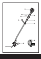
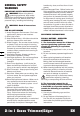
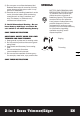
1. Auxiliary Handle 2. Three Speed Settings 3. Lock Off Switch 4. Battery Pack 5. On/Off Lever 6. Shaft Locking Knob 7. Auxiliary Handle Locking Clamp 8. Safety Guard 9. Edge Guide 10. Line Cutter 11. Trimmer Head Cover (See Fig. I2) 12. Cap Release Latch (See Fig. I2) 13. Spool (See Fig. I2) 14. Trimmer Head (See Fig. I2) 15. Eyelet (See Fig. I2) 16. Line Feed Button (See Fig. I1) 6 Not all the accessories illustrated or described are included in standard delivery.
TECHNICAL DATA Voltage No load speed Cutting diameter 40V Max* 8300/min 13”(330mm) Line diameter 0.08”(2.0mm) Charging time 1hr Machine weight 7.7 lbs(3.5kg) * Voltage measured without workload. Initial battery voltage reaches maximum of 40 volts. Nominal voltage is 36 volts. Accessories Charger (WA3734) battery pack (WA3536) spool (WA0014) 1 1 1 We recommend that you purchase your accessories from the same store that sold you the tool.
GENERAL SAFETY WARNINGS Important Safety Instructions WARNING! When using electric gardening appliances, basic safety precautions should always be followed to reduce the risk of fire, electric shock, and personal injury, including the following: WARNING: Read all instructions 8 FOR ALL APPLIANCES 1) Avoid Dangerous Environment - Don’t use appliances in damp or wet locations. 2) Don’t Use In Rain. 3) Keep Children Away - All visitors should be kept at a distance from work area.
3) Do not open or mutilate the battery(ies). Released electrolyte is corrosive and may cause damage to the eyes or skin. It may be toxic if swallowed. 4) Exercise care in handling batteries in order not to short the battery with conducting materials such as rings, bracelets, and keys. The battery or conductor may overheat and cause burns. 3. Avoid Unintentional Starting – Do not insert battery with finger on switch. Be sure switch is off when inserting battery.
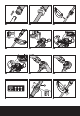
ASSEMBLY 1. ASSEMBLY OF THE MAIN HANDLE (See Fig. A1, A2) Align and insert the shaft into the upper housing until a click can be heard. Make sure the grooves are correctly matched. (See Fig. A1). Tighten the shaft locking knob in the direction indicated to lock (See Fig. A2). Note: Make sure that the handle is firmly locked in place. 2.ASSEMBLY OF THE AUXILIARY HANDLE (See Fig. B1, B2) Slide the auxiliary handle onto the grooves of auxiliary handle support until a click can be heard.
prevent accidental starting. Depress the Lock OFF switches and the On/OFF lever (5) to start your trimmer. To switch off, just release the on/ off switch. Warning! The cutting head continues to rotate after the trimmer has been switched off; wait until it has completely stopped then lay down the tool. Warning: Use only 0.08”(2.0mm) diameter cutting line. Other sizes of line will not feed properly and will result in improper cutting head function or can cause serious injury.
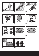
Repeat above until you hear the lines hitting against the line cutter. To manually feed the line (See Fig. I1) ALWAYS REMOVE THE BATTERY PACK BEFORE ADJUSTING THE TRIMMER HEAD POSITION. If required, line can be feed out manually To operate, press and release manual line feed button (16), while gently pulling out the line until it is long enough to reach the line cutter. If the line extends past the line cutter, too much line has been fed out.
Troubleshooting The following table gives checks and actions that you can perform if your machine does not operate correctly. If these do not identify and correct the problem, contact your service agent. Warning: Switch the machine off and remove the battery prior to any troubleshooting. Problems Possible Causes Corrective Action Trimmer fails to operate. Battery discharged. Battery too hot/cold. Motor is broken. Internal wiring of machine damaged.