
Instruction manual


PV820/PV830 Pneumatic PicoPump
World Precision Instruments 21
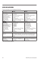
APPENDIX A: FLOW DIAGRAMS
The following diagrams depict how air and vacuum are routed through the PV820
and PV830 pumps.
Air
Source
Solenoid
Trigger/
Timing
HOLD PRESSURE
EJECT PRESSURE
vac
pressure
atmosphere
vent
hold
Vaccum Port Output
(vacuum or air)
Eject Port Output
(output of the solenoid = vacuum,
e
j
ect
p
ressure or hold
p
ressure
)
Vacuum
Source
PV820
Fig. 15— Air and vacuum fl ow through the PV820 based on the switch settings, and the air
pressure (for both the hold and eject) is regulated.
Air
Source
Solenoid
Trigger/
Timing
VACUUM
HOLD
EJECT
VAC ATM VAC HOLD
Vaccum Port Output
(vacuum or air)
Eject Port Output
(output of the solenoid = vacuum,
eject pressure or hold pressure)
Vacuum
Source
atmosphere
PV830
Fig. 16— Air fl ows through the PV830 based on the switch settings, and the air pressure (for
both hold and eject) and vacuum are regulated.