EN Operating and installation instructions for RADEMACHER tubular motors ....................................... 27 Applicable for the following series: RolloTube Intelligent Small/Medium Item numbers: 2640 06 95 / 2640 10 95 / 2660 10 95 / 2660 20 95 / 2660 30 95 / 2660 40 95 / 2660 50 95 Please note: Site of installation: ................................................................................................................................. Serial number: ......................................
i EN Dear Customers, CE Mark and Conformity With your purchase of this tubular motor, you have decided in favour of a quality product manufactured by RADEMACHER. We would like to thank you for your confidence. This product fulfils the requirements of all applicable European and national directives. RADEMACHER tubular motors have been developed with the greatest possible convenience in mind.
i Contents EN Dear Customers,.............................................................................................28 These instructions...........................................................................................28 Key to symbols...............................................................................................28 Illustrations....................................................................................................30 Key to the overall view (Figure ) . .......
i EN Illustrations 1 (1) (2) (3) (5) (4) (6) (7) (8) (9) (10) (11) (12) (13) (14) (15) (17) 2 3 4 (16) (8) (18) (7) (19) L B C A = (D/2) 5 L = A - (B + C) (10) (10) (5) (2) (8) (3) (9) (5) (4) (5) 7 6 (1) (4) (5) 8 (5) (6) (20) SW 40 (20) (11) (12) (13) (14) (2) (6) 30
EN Key to the overall view (Figure ) (1) (2) (3) (4) (5) (6) (7) (8) (9) (10) (11) (12) (13) (14) (15) (16) (17) (18) (19) (20) Counter bearing Ball bearings Axle pin on bearing capsule Bearing capsule Rotating union Fastening spring Retaining clip Catch Tubular motor Adapter Set button Drive head Drive end bearing Retainer Motor cable Controller (e.g.
EN General safety instructions Danger due to electric shock when working on all electrical systems. Incorrect use leads to an increased risk of injury. ◆◆ The electrical connection for the tubular motor and all work on the electrical systems may only be undertaken by an authorised qualified electrician and in accordance with the connection diagrams in these instructions, see pages 41/42). ◆◆ Train all personnel to safely use the tubular motor.
i EN Functional description The RADEMACHER Intelligent series of tubular motors are designed for opening and closing roller shutters and awnings. RolloTube Intelligent tubular motors are equipped with the new Safe-Drive system for position detection, torque monitoring and obstacle detection. The drive's compact design and fully automatic end point configuration ensures for straightforward and convenient installation.
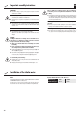
EN Important assembly instructions IMPORTANT ◆◆ Check that the voltage / frequency on the type plate corresponds to local mains conditions prior to installation. Only use tubular motors which correspond to the local conditions in terms of their power. Incorrectly dimensioned tubular motors can lead to damage. ◆◆ All cables and equipment not required for operation of the equipment is to be removed or deactivated prior to installation of the tubular motor.
EN Mounting the bearing (Figure ) 1. Check that the bearing is installed horizontally. Roller shutters wound at an angle can block the drive and cause damage. 1. IMPORTANT When installed, the wound roller shutter must run vertically in the guide rails on the window. First determine the position of the drive (13) and counter bearing (1) in the roller shutter box. 2. Fasten the bearing in accordance with the bearing type and on-site conditions.
Mounting the catch with freewheel mechanism (Figure EN )* * = supplied state 4.a IMPORTANT If the tubular motor is to be operated with automatic end point configuration and obstacle detection, then the catch (8) must be mounted with free-wheeling action. (19) (8) 1. Slide the catch (8) onto the limit ring (19) so that it can free-wheel and so that it engages behind the retaining clip (7). Free-wheeling is given if the catch (8) can be easily turned back and forth.
Sliding the tubular motor into the rotating union (Figure ) Never knock the motor (9) with force into the rotating union (5). STOP 1. EN Doing so will cause serious damage. First slide the catch (8) into the rotating union (5). 2. Subsequently, press the rotating union (5) fully onto the adapter (10). IMPORTANT In doing so, ensure that the adapter (10) does not slip off of the limit ring (18) on the drive head (12) during the assembly process. Otherwise malfunctions may occur, see page 49.
Preparation for use of precision tubes (Figures - ) EN 5.d 3. Slide the tubular motor into the precision tube. 5.e 4. Mark the four fastening holes and subsequently drill them through the precision tube in the catch (8). ATTENTION ◆◆ Never drill deeper than 10 mm into the catch (8). ◆◆ Never drill in the area of the drive. Doing so will cause serious damage. STOP 5.f 5. Inserting the bearing capsule (Figure ) 1.
Mounting the motor into the bearing (Figure ) 1. 2. Drive bearing (as click bearing)/(13) EN Counter bearing (1) Press the drive head (12) lightly onto the drive bearing (13) until it engages. Insert the other end of the rotating union (5) with the ball bearing (2) into the counter bearing (1). NOTE In the event that you are using a different bearing to the RADEMACHER click bearing, you may need to secure the drive with a secondary cotter pin. The set button (11) must be easily accessible.
EN Safety information regarding the electrical connection Danger due to electric shock when working on all electrical systems. Fixed-installation devices... ◆◆ The electrical connection for the tubular motor and all work on the electrical systems may only be undertaken by an authorised qualified electrician and in accordance with the connection diagrams in these instructions. ...must be equipped on the installation side with a circuit-breaker for each phase in accordance with DIN VDE 0700.
Electrical connection of the tubular motor (Figure k) EN Control of a drive from a single point with a 1-pole switch / button 11 Legend (a) (a) (b) (c) (d) = = = = set button (11) Controller (e.g.
Connection of an external button (230 V/50 Hz) (Figure m) ... EN ...for subsequent adjusting the end point with the set line 13 Legend (a) (a) (b) (c) (d) (j) = = = = set button (11) Controller (e.g.
EN End point adjustment Mortal danger due to tearing off the motor cable (15). Ensure that the motor cable (15) is not taken up by the rotating union (5) or torn off during the configuration process. You have various options for configuring the end points, which are described in the following section: ◆◆ Automatic configuration of the end points. ◆◆ Manual configuration of the end points: - Manually setting the upper end point and setting the lower end point by means of obstacle detection.
EN Manual adjustment of end points IMPORTANT ◆◆ Operating the equipment without a stopper (21) may cause the roller shutters to run into the roller shutter box and be damaged. Initial installation For initial installation, the roller shutter engineer can carry out the end point configuration with the help of the set button (11) on the motor or with a commercially available cord switch device (22). The roller shutters must always be fitted with a stopper (21) or end-rail.
Automatically setting the upper end point and manually setting the lower end point EN 1. The roller shutters will travel to the upper stop until the tubular motor switches off automatically. ▲ ▼ Afterwards, the tubular motor will reverse and the roller shutters will move downwards. 2. 3. 4. IMPORTANT Never interrupt the sequence while the process is running. The roller shutters must be allowed to travel up without interruption.
EN Manually setting the upper / lower endpoints 1. 2. ▲ ▼ SET or First set the switch / controller to upward travel (s) / downwards travel (t). NOTE In the event of incorrect direction of rotation, disconnect the lead from the mains and exchange wires L1 and L1 . Press and hold the corresponding set button* until the desired end point is reached. The roller shutters travel up / down. * on the motor, the cord switch device (22) or the external switch. 3. 4.
EN Configuring tubular motors The tubular motors can be individually configured with the help of a cord circuit setting unit (22). The following configurations are possible. NOTE Further settings can be undertaken with the help of the optionally available RT ConfigTool. Please refer to the information on our Website in relation to this (www.rademacher.de). ◆◆ Reload the factory settings. ◆◆ Switching the reversing mechanism after obstacle detection on / off.
Switching the reversing mechanism on / off after obstacle detection 1. 1. SET + 2. 10 s EN First press and hold the SET button on the cord circuit setting device (22) and subsequently press and hold the up or down button for 10 seconds. After 10 seconds the reversing function will be switched on or off. Factory setting = reversing is switched on. 2. After approx. 10 seconds the tubular motor acknowledges switching on / off of the reversing function by briefly starting up.
i EN What to do if... ? ...The set line is not available locally and the SET button on the tubular motor is not accessible, however, the end points should be manually configured. ...the motor fails to start? Possible cause: ◆◆ Mains power not available. Solution Solution: ◆◆ In order to carry out this configuration, it is necessary to connect both control lines for up (s) and down (t) separately to the phase (L).
i EN What to do if... ? ...The set line is not available locally and the SET button on the tubular motor is not accessible, however, the factory settings are to be loaded. Solution ◆◆ In order to carry out this configuration, it is necessary to connect both control lines for up (s) and down (t) separately to the phase (L). ◆◆ Either use an external button with two switching contacts or the commercially available cord circuit set device (22).
i Small Motor series Type: i EN Technical specifications 6/28 6 28 230 50 121 0.53 4 5 0.75 3 32 H I IP 44 PVC 485 35 3 Medium 10/16 10 16 230 50 121 0.53 4 5 0.75 3 32 H I IP 44 PVC 485 35 3 10/16 10 16 230 50 112 0.49 4 5 0.75 3 32 H I IP 44 PVC 487 45 2 20/16 20 16 230 50 145 0.64 4 5 0.75 3 32 H I IP 44 PVC 487 45 2 30/16 30 16 230 50 191 0.83 4 5 0.75 3 32 H I IP 44 PVC 546 45 2 40/16 40 16 230 50 198 0.86 4 5 0.75 3 32 H I IP 44 PVC 546 45 2 50/12 50 12 230 50 205 0.89 4 5 0.
i Warranty conditions EN RADEMACHER Geräte-Elektronik GmbH provides a 5 year guarantee for new equipment installed in accordance with the installation instructions. All construction faults, material defects and manufacturing defects are covered by the warranty.