
Instructions


52
EN
i
2.
1.
3.
▲
▼
▲
▼
1 x 0,5 s
4.
▼
▲
5.
▲
▼
6.
▼
▼
1 x 0,5 s
1.
2.
3.
What to do if... ?
...the motor fails to start?
Possible cause:
◆ Mains power not available.
Solution:
◆ Check the power with a meter to ensure that the supply voltage (230 V) is available
and check the wiring.
◆ Observe especially the information relating to impermissible connection types.
...the wiring is incorrect?
Possible cause:
◆ The control lines are mixed up.
Solution:
◆ Disconnect the lead from the mains and exchange wires for L1 and
L1 .
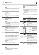
...The tubular motor stops after a short period of time during the
configuration and test procedures?
Possible cause:
◆ The adapter (10) may have slipped off of the magnetic ring (18) on the drive
head (12).
Solution:
◆ Check that the adapter (10) sits flush with the drive head (12) and is fully inserted
into the rotating union (5).
◆ Slide the adapter (10) back so that it is flush with the drive head (12) and slide
the rotating union (5) fully onto the adapter (10), see Figure
. Re-adjust the end
points if necessary, see page 46.
...Automatic adjustment of the lower end point does not work.
Possible cause:
◆ The catch (8) is mounted without the freewheel mechanism.
Solution:
◆ Configure the lower end point manually, see page 49.
...The tubular motor stops between the two end points during normal
operation?
Possible cause 1:
◆ The bearing capsule (4) may not be secured with a screw to the rotating union (5)
(see Figure ), causing the rotating union (5) to slip from the motor and the adapter
(10) to come away from the magnetic ring (18) on the drive head (12).
Solution 1:
◆ Check for correct fitting of the bearing capsule (4) and the adapter (10). Use a
self-locking bolt to secure the bearing capsule (4) to the rotating union (5) and
remount the motor in accordance with the information on pages 36 - 41.
Possible cause 2:
◆ The thermal protection system has triggered.
Solution 2:
◆ Wait approx. 20 minutes until the motor has cooled down.
...The roller shutters stop during upward or downward travel?
Possible cause:
◆ Iced-up roller shutters or obstacle on the guide rail.
Solution:
◆ Move the roller shutters a short distance in the respective opposite direction.
◆ Rectify iced-up roller shutters or obstacle.
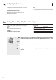
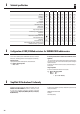
...The set line is not available locally and the SET button on the tubular
motor is not accessible, however, the end points should be manually
configured.
Solution
◆ In order to carry out this configuration, it is necessary to connect both control lines
for up (▲) and down (▼) separately to the phase (L).
◆ Either use an external button with two switching contacts or the commercially available
cord circuit set device (22).
◆ Always have the connection work carried out by a specialist elec-
trician and observe the safety information relating to the electrical
connection on page 42.
NOTE
Further information can be obtained from our Website at www.rademacher.de.
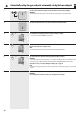
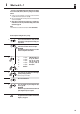
Brief instructions for configuring the upper end point.
Once the electrical connection is made, determine
the direction of rotation by means of briefly press-
ing the button.
Press and hold the up (▲) button.
If the roller shutters are not yet at the upper end point, then they
will now travel up to this position.
NOTE
If the roller shutters are at the upper end point, then you must
first move the roller shutters down.
Additionally, briefly press
the down (▼) button 2
times for 0.5 seconds
each time and on the
third press, hold the
button down.
hold down
Release both buttons immediately as soon as the
desired upper end point has been achieved. The end
point is thereby stored.
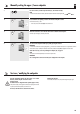
Set the lower end point if necessary.
NOTE
Configuration for the lower end point is undertaken in the same
way as for the upper end point. In order to do so, ensure that
you first press the down (▼) button and then press the up
(▲) button.
Switch off the mains power supply and re-configure
the original connection in accordance with connection
diagram n on page 43.