
Instructions

EN
48
15
(a)
(b)
(c)
(d)
(e) (f) (g) (i)(h)
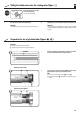
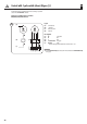
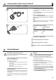
Legend
(a) = set button (11)
(b) = 1-pole switch
(c) = Mains 230 V/50 Hz
(d) = Socket box
Pin assignment
(e) = PE green/yellow
(f) = N blue
(g) = L black
(h) = external switch white/grey *
(i) = Antenna brown
* maximum cable length between tubular motor and external switch = 10 m
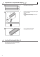
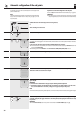
Control with 1-pole switch (closer) (Figure
o
)
IMPORTANT
◆ If the “external switch” (h) lead is not used, then it must be connected to the neutral conductor (f)
(see fig. n).
The radio tubular motor can be controlled locally by means of connecting a 1-pole switch
(closer) to the “external switch” conductor.
In doing so, the switching sequence is as follows:
OPEN/STOP/CLOSE/STOP, and so on.