
Instructions


EN
46
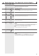
Release the set button (7) as soon as the awning has reached the desired position.
The motor stops and the lower end point is stored.
Subsequently the drive shifts the awning in the opposite direction.
Press and hold the set button (7) on the motor until the lower end point is reached.
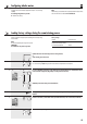
Symbols and actions when connecting a cord circuit setting unit (20)
or
when connecting an external switch.
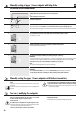
Automatically setting the upper end point and manually setting the lower end point
The awning will first retract to the upper stop until the tubular motor switches off automatically.
If the tubular motor is already logged on to the DuoFern network, then the direction of travel can also be specified with DuoFern transmitters.
IMPORTANT
◆ Never interrupt the sequence while the process is running. The awning must retract without interruption.
◆ The awning must retract first. If the awning first extends, then the direction of travel must first be reversed by pressing the SET button
several times or by using the external switch.
◆ The switching sequence for the SET button or the external switch is: Retract/stop/extend/stop, and so on.
You can correct the lower end point in small steps by briefly pressing the set button (7).
IMPORTANT
◆ In the event that a malfunction occurs during configuration, e. g. in the event that the tubular motor only runs for a single rotation even
when the set button is pressed, it is unlikely that the tubular motor is faulty. Possibly the adapter (8) has slipped off of the drive head (6).
◆ Check and, if necessary, correct the positioning of the adapter (8), (see page 50).
NOTE
In the event that the end point configuration fails, you must reset the tubular motor to the factory setting (see page 49), in order to repeat
the process.
6.
4.
5.
2.
3.
7.
or
OFF
ON
or
1.
SET
or
ON
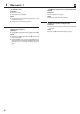
Switch on the mains power.
Finally, disconnect the tubular motor from the mains for a few seconds. Subsequently, the tubular motor is ready
for operation.
NOTE
The fabric relief and tensioning systems are only active if the end points have been configured as described above.
IMPORTANT
◆ The external switch lead (h) must be connected to neutral conductor (f) after configuration of the end points.