WS Technologies Inc. Beacon Monitor Operator’s Manual for model: FBM200A Version 1.
Information contained in this manual is subject to change without notice. Please consult the website at www.wst.ca for new Operator’s Manual updates. Complying with all applicable copyright laws is the responsibility of the user.
CONTENTS INTRODUCTION ................................................................................................. 1 UNPACKING ....................................................................................................... 1 BEACON MONITOR ........................................................................................... 2 Antenna Connection: ....................................................................................... 3 Optional Outdoor Antenna Installation: ................
iv
INTRODUCTION Thank you for choosing the FBM200 Beacon Monitor. This Operator’s Manual describes the installation and operation of the Beacon Monitor. UNPACKING Lift up on the inner fold on the right side of the Beacon Monitor box and remove the Beacon Monitor from the underside. The accessories are in the box on the right. Be sure to keep the accessories box for handy storage of the Beacon Monitor Operator’s Manual and accessories when not in use. Please verify the contents of your package.
BEACON MONITOR Please read this Operator’s Manual to become familiar with the operation of the Beacon Monitor.
Antenna Connection: Connect the 406 MHz antenna to the front panel RF IN connector. Optional Outdoor Antenna Installation: Alternatively, if you have purchased the optional outdoor antenna, install the outdoor antenna following the mounting instructions included with the antenna. The U-bolts will fit a mast from approximately 1.25” to 2.50” in diameter. Connect the Antenna Extension cable between the antenna and the RF IN connector on the Beacon Monitor.
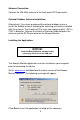
The Beacon Monitor Setup screen will appear. Click Next. TM If Java is not installed on your computer, you will be prompted to install it. Follow all on-screen instructions. Once completed click Finish. The Beacon Monitor icon will appear on your computer.
SETTING UP THE APPLICATION Click on the Beacon Monitor icon. The Beacon Monitor application will start and the following screen will be displayed: The Connection Status in the Status section shows a red X, indicating the receiver is not connected. Connect the FBM200 receiver to a USB port on the computer using the supplied USB cable. This connection is both the power supply and the communication link to the unit.
Full Screen button Monitor Mode: Monitor button Beacon burst log area Setup button Status section Beacon burst decode area Monitor button The Monitor button will switch the screen to the Monitor mode. This is the normal mode for monitoring beacon burst activity. Setup button The Setup button will switch the screen to the Setup mode. This mode allows the user to setup the application and receiver as needed.
includes date and time of beacon burst, beacon 15 Hex ID, country code, beacon transmit frequency, receive level of beacon signal, and a comments field. All of the information is sortable by clicking on the header of the column that you wish to sort. Double click in the comments field to add or modify a comment. Beacon Decode area The Beacon Decode area shows the decoded message details for any selected burst. Full Screen button To maximize the Beacon Monitor screen click the Full Screen button.
Setup Mode: Clicking on the Setup Button will take you to the Setup mode. Setup button Setup panel Setup menu Setup Menu The setup menu has a selection of items. See details of each section in the Setup Items section below. Single click on each heading in the Setup menu to collapse or expand the section under each heading. Setup panel The Setup panel is the information or setup area for each item in the Setup menu.
Receiver Sensitivity Slider bars button Apply button The receiver sensitivity can be adjusted for each application. To receive beacon bursts from far away, set the sensitivity to the highest level of -125 dBm. This setting will receive bursts from near also. To receive only the beacons that are near, set the sensitivity to the lowest level of -55 dBm. The default sensitivity level is -115 dBm. The Beacon Monitor has sophisticated algorithms for preventing false triggering.
Alarms Computer Alarms There are three alarm notification methods on the computer; Visual Alarm, Alarm Pop-up, and Audio Alarm. When an alarm notification is triggered by a received burst, an Alarm Reset button appears below the Setup button. To clear the alarm, click on the Alarm Reset button. Visual Alarm A red “ALERT” will flash at the top of the screen. Alarm Reset button This alarm is reset using the Alarm Reset button.
Alarm Pop-up A pop-up notification will appear in front of any application running on the computer. The Pop-up notification is closed by clicking on the X. Audio Alarm An Audio Alarm will sound through the computer audio system. This alarm is reset using the Alarm Reset button. All 406 MHz beacon bursts are encoded as either: 1. Normal Mode (Live Burst) 2. Self Test mode 3. Test Protocol The user has the option to set each alarm notification method based on the mode of the received beacon burst.
Receiver Alarms Audio/LED/Relay Alarm The receiver audio alert will sound, the LED Indicator will flash red, and the relay contacts will close when a burst is received. The user has the option to set each receiver alarm notification method based on the mode of the received beacon burst. Check or un-check the boxes on the Receiver Alarms setup page to suit your requirements. These alarms are reset by clicking the Alarm Reset button on the application or pressing the Reset button on the receiver.
Alerts E-Mail Alerts Email alerts can be automatically sent to 2 email addresses. Check or un-check the boxes on the E-mail Alerts setup page to suit your requirements. In the Sender Information section enter your Company Name. This information will appear on the email report. Enter the Email Address. This will be the email address the email will show originating from. Enter Server Information for your outgoing mail server. Contact your network administrator for this information.
SMS Alerts SMS Text Messaging alerts can be automatically sent to two numbers. Check or un-check the boxes on the SMS Alerts setup page to suit your requirements. In the Sender Information section enter your Company Name. This information will appear on the email report. Enter the Email Address. Enter Server Information for your outgoing mail server. Contact your network administrator for this information. Enter the phone number and the gateway server information. Refer to the website: http://en.wikipedia.
Enter any addition information desired in the Message field. Click Apply to save the changes. Click Test to send a SMS message. NOTE: You are responsible for any charges incurred relating to SMS messages.
Help About Beacon Monitor The About Beacon Monitor screen shows Receiver Information including model number, serial number, Receiver firmware version, and internal temperature, and Beacon Monitor Software revision. Check for Updates button Check for Updates The Beacon Monitor software will check for updates automatically. When a software update is available a pop-up notification will prompt you through the update.
RECEIVING BURSTS Once your system is setup you should always verify reception by transmitting a self test burst from a 406 MHz beacon. All bursts that are received are logged and recorded. When a burst is a Normal Mode (Live Burst) the entire line item will be highlighted in red (see Index item #7 below). If another Normal Mode burst is received it will be highlighted in red and the previous burst highlight will change to pink.
FREQUENTLY ASKED QUESTIONS Q: How do I manually check for software updates? A: Go to Setup > About Beacon Tester. Click on the Check for Updates button. Q: Do I need internet access to run Beacon Monitor? A: Internet access is required to download and install the Beacon Monitor application; for the program to determine if software updates are available; and to send Email or SMS messaging notifications.
SPECIFICATIONS BEACON MONITOR FBM200A SPECIFICATIONS SPECIFICATIONS 406 MHz Receiver Sensitivity Out of Band Rejection (<400 MHz, >413 MHz) Harmonic Image Rejection 406 MHz Input Frequency 406 MHz RF Input VSWR 406 Input Impedance 406 Input Connector Receiver power requirements (from USB port) Operating Temperature Range Storage Temperature Range -125 dBm >145 dB >95 dB 406.0 – 406.1 MHz 1.20:1 50Ω SMA-female RP +5V @ <500 mA -40°C to +85°C -55°C to +85°C 108 x 63 x 26 mm 4.3 x 2.5 x 1.0 inches 0.
REGULATORY INFORMATION CANADA This Class B digital apparatus complies with Canadian ICES-003. USA Note: This equipment has been tested and found to comply with the limits for a Class B digital device, pursuant to part 15 of the FCC Rules. These limits are designed to provide reasonable protection against harmful interference in a residential installation.
EUROPEAN UNION DECLARATION OF CONFORMITY Supplier Name: WS Technologies Inc. Supplier Address: #2 – 215 Neave Road Kelowna, B.C. Canada V1V 2L9 Declares under our sole responsibility that the following product Product Name: 406 Beacon Monitor Model FBM200 Conforms to the following normative European and International Standards Normative: Standards: EN 301 489-1 V1.9.
WARRANTY INFORMATION WS Technologies Inc. (WST) warrants the products manufactured by WST to be free from defects in material and workmanship for one year from the date of shipment.
MISSION CONTROL CENTER (MCC) CONTACT INFORMATION In the event that you believe a Normal Mode (Live Burst) has been transmitted with sufficient power to cause a false alert, the nearest Mission Control Centre (MCC) should be contacted. Please refer to the following list for the MCC in your country.
NOTES Enter important data here for future reference.