
User's Manual

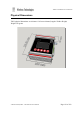
Table Of Contents
- Introduction
- Safety Information
- Operation
- Buttons
- Main Screens
- Site Configuration Tools
- Two-Way Paging
- Configuration Methods
- MENU Configuration
- Serial Command Configuration
- Protocols
- SCADA Support
- IO Mirror Operation
- Input Handling
- Output Handling
- WTE Output Control Protocol
- WTE Ack and Confirm Protocol
- Store Forward Operation
- Installation
- Input Output Hardware Connection
- Serial Connections
- RF Connections
- Power Connections
- Ethernet Interface
- TReX Firmware Upgrade
- Physical Dimensions
- Mounting Hardware
- Omni or Directional Antenna
- Antenna Elevation
- Disclaimer
- Manufacturing marking and labels
- Maintenance
- Product End Of Life
- Product Warranty
- Abbreviations and Glossary
- Specifications

TReX User Manual v2.14 Firmware
RF Connections
A 50 ohm matched load must be fitted to the TReX antenna port.
Note: Earth the antenna tower, feeders and lightning protection devices in accordance with the
appropriate local and national standards. Use grounding kits as specified or supplied by the
coaxial cable manufacturer to properly ground or bond the cable outer.
!CAUTION
When the TReX is operating, there is RF energy radiated from the antenna.
Do not stand in front of the antenna while the radio is operating (see the ‘RF Exposure Warning’)
!CAUTION
Lightning will destroy electronic equipment.
To avoid this risk, install primary lightning protection devices on any interfaces that
are reticulated in the local cable network.
You should also install a coaxial surge suppressor on the radio antenna port.
© WTE Limited, 2018 – Christchurch New Zealand Page 134 of 158