
User's Manual
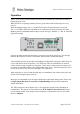
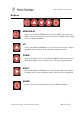
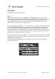
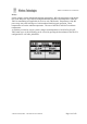

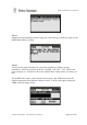

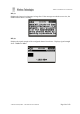
Table Of Contents
- Introduction
- Safety Information
- Operation
- Buttons
- Main Screens
- Site Configuration Tools
- Two-Way Paging
- Configuration Methods
- MENU Configuration
- Serial Command Configuration
- Protocols
- SCADA Support
- IO Mirror Operation
- Input Handling
- Output Handling
- WTE Output Control Protocol
- WTE Ack and Confirm Protocol
- Store Forward Operation
- Installation
- Input Output Hardware Connection
- Serial Connections
- RF Connections
- Power Connections
- Ethernet Interface
- TReX Firmware Upgrade
- Physical Dimensions
- Mounting Hardware
- Omni or Directional Antenna
- Antenna Elevation
- Disclaimer
- Manufacturing marking and labels
- Maintenance
- Product End Of Life
- Product Warranty
- Abbreviations and Glossary
- Specifications

TReX User Manual v2.14 Firmware
Main Screens
The TReX top icon bar provides information about the display screen and operating
status. .The far right text indicates the selected main screen. This is either “IO” (inputs and
outputs), “TX” (transmit) or “RX” (receive).
The far left icon indicates system voltage as a proportion of the configured high and low
battery levels (MENU->INPUTS->BATT HIGH/LOW V).
The “X” icon is visible when no messages have been received for 2 minutes and on start-up.
The time in the middle is the current RTC time (MENU->SYSTEM->TIME).
The “S” letter indicates that the master or slave SCADA telemetry modes are in operation.
The “M” letter, when present indicates that a Modbus telemetry request packet has been
processed within the last 2 seconds.
The “Incoming” down arrow indicates that the TReX is receiving (absent when
RX is DISABLED). The “Outgoing” up arrow indicates that the TReX is
transmitting (if a transmitter enabled TReX).
The Icon “T” below indicates the TReX has been configured for telemetry stand-
alone “Back-to-Back Mirror Mode”.
The back to back arrows indicate the unit is operating in “Serial Link”
Telemetry mode.
© WTE Limited, 2018 – Christchurch New Zealand Page 14 of 158