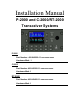
Installation Manual P-2000 and C-2000/RT-2000 Transceiver Systems P-2000 Part Number: 400-049200-11-xxx-xxxx-xxxx Hardware Mod: 1 C-2000 Part Number 400-049300-11-xxx-xxxx-xxxx Hardware Mod: 1 RT-2000 Part Number 400-049400-11-xxx-xxxx-xxxx Hardware Mod: 1
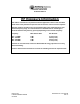
P-2000/C-2000/RT-2000 Installation Manual RF Exposure Information This radio is restricted to occupational/controlled applications where users have been made aware of the potential for exposure and can exercise control over their exposure. Antennas used for the radio must not exceed the antenna gain shown below for each transmit frequency range. The antenna must be installed at least or exceeding the minimum distance away from any person(s) depending on the transmit frequency.
P-2000/C-2000/RT-2000 INSTALLATION MANUAL SECTION 1 – GENERAL INFORMATION 1. Introduction This section contains information relative to the physical, mechanical, and electrical characteristics of the Wulfsberg Electronics “2000” Family of Communications Systems. 2. Applicability This manual applies only to the P-2000 panel mount transceiver, C-2000 control unit, and RT2000 remote mount transceiver. 3.
P-2000/C-2000/RT-2000 Installation Manual on this input may need to be increased to 20 AWG. All other microphone inputs/headset outputs and backliting are compatible. B. C-2000 Control Display Unit The Wulfsberg C-2000 is a control display unit that can be used as a slave control head with a P-2000 panel mount transceiver, or as a primary or slave control head for the RT- 2000 remote transceiver. Versions of the C-2000 include black faceplate and options for either Standard or NVG compatible displays.
P-2000/C-2000/RT-2000 INSTALLATION MANUAL 4. Technical Characteristics A.
P-2000/C-2000/RT-2000 Installation Manual Channel Spacing Receiver Specifications Modes Sensitivity Analog (12 dB SINAD) Digital (5% BER) Quieting Analog (20 dB SINAD) Digital Selectivity Analog (12.5 kHz) Analog (25.0 kHz) Intermod Rejection Analog (12.5) Analog (25.0) Spurious Rejection Analog (12.5 kHz) Analog (25.
P-2000/C-2000/RT-2000 INSTALLATION MANUAL Sidetone Output Publication No. 150-049106 Rev. A Adjustable 0 to –30 dB below rated output.
P-2000/C-2000/RT-2000 Installation Manual B.
P-2000/C-2000/RT-2000 INSTALLATION MANUAL Temperature Range Operation Storage Cooling Weight RT-2000 (Single Transceiver) RT-2000 (Dual Transceiver) Mounting Overall Dimensions Height Width Length Input Power Requirements Normal Voltage Range Abnormal Voltage Range Emergency Operation RT-2000 (Single Transceiver) Receive Transmit RT-2000 (Dual Transceiver) Receive Transmit Frequency Band P-2000/RT-2000 Data Bus Encryption Options OTAR Options Trunking Options Receiver Specifications Modes Sensitivity Anal
P-2000/C-2000/RT-2000 Installation Manual Spurious Rejection Analog (12.5 kHz) Analog (25.0 kHz) Digital (5% BER) Unwanted Emissions Narrow Band Wide Band Frequency Stability Audio Output Headset Out Normalized Out External Speaker Out Audio Distortion Hum and Noise Unsquelched Squelched Transmitter Specifications Duty Cycle RF Power Output Frequency Stability Modulation Limiting: 12.5 kHz Channels 20.0 kHz Channels 25.
P-2000/C-2000/RT-2000 INSTALLATION MANUAL 5. Available Configuration Variations A.
P-2000/C-2000/RT-2000 Installation Manual | 6 = 380 - 470 MHz |-----Reserved (Always marked "0") B. C-2000 Part Number Matrix 400-049300-AB-CDE A: B: C: D: E: Major Hardware Version 1 = Initial Release Major Software Version 1 = Initial Release Reserved for future use (Always marked "0") Faceplate Option 1 = Black Face Plate 2 = Grey Face Plate Display Option 1 = Standard Display 2 = NVG Compatible Display Page 12 of 41 P-2000 Installation Manual Oct 2003 Publication No. 150-049106 Rev.
P-2000/C-2000/RT-2000 INSTALLATION MANUAL C.
P-2000/C-2000/RT-2000 Installation Manual D. Antenna Options The following antennas are required for use with the P-2000/RT-2000 Transceivers. Antenna Name Wulfsberg Part Number 121-0019-000 121-014378-01 121-019079-01 AT-695 AT-462 AT-806 Frequency Band FAA Certification 136-174 MHz 380-520 MHz 806-870 TSO PMA TSO See Figure 2-1, 2-2,2-3 for envelope drawings of antennas. E. RT-2000 Mounting Tray (Wulfsberg P/N 300-XXXXXX-01) See Figure 2 –4 for envelope drawing of RT-2000 Mounting Tray. F.
P-2000/C-2000/RT-2000 INSTALLATION MANUAL SECTION 2 – INSTALLATION 1. General This section contains suggestions and factors to consider before installing the P-2000/C2000/RT-2000. Close adherence to these suggestions will assure a more satisfactory performance from the equipment. 2. Unpacking and Inspecting Equipment Exercise extreme care when unpacking the equipment. Make a visual inspection of the units for evidence of damage incurred during shipment.
P-2000/C-2000/RT-2000 Installation Manual (2) The installing agency will supply and fabricate all external cables. The connectors are supplied separately and are listed in Section 1.F. (3) The length and routing of the external cables must be carefrully studied and planned before attempting actual installation. Avoid sharp bends and placing cables too near other aircraft cables. (4) Use only recommended wire sizes and wire type for interwiring.
P-2000/C-2000/RT-2000 INSTALLATION MANUAL E. Antenna Mechanical Installation (1) Antenna installation is critical to the range and quality of the transmitted signal. Care should be taken to keep all antennas a separated as possible. A minimum of 70 cm should be observed if possible. (2) Whenever possible, mount antennas on the bottom of the aircraft.
P-2000/C-2000/RT-2000 Installation Manual This page intentionally left blank. Page 18 of 41 P-2000 Installation Manual Oct 2003 Publication No. 150-049106 Rev.
P-2000/C-2000/RT-2000 INSTALLATION MANUAL Remove this page and insert 154-049200 (P-2000 outline), Sheet 1 of 1 (Fig. 2-1). Publication No. 150-049106 Rev.
P-2000/C-2000/RT-2000 Installation Manual Remove this page and insert 154-049300 (C-2000 Outline), Sheet 1 of 1 (Fig. 2-2). Page 20 of 41 P-2000 Installation Manual Oct 2003 Publication No. 150-049106 Rev.
P-2000/C-2000/RT-2000 INSTALLATION MANUAL Remove this page and insert 154-049400 (RT-2000 Outline), Sheet 1 of 1 (Fig. 2-3). Publication No. 150-049106 Rev.
P-2000/C-2000/RT-2000 Installation Manual Remove this page and insert 154-049065 (RT-2000 Mounting Tray), Sheet 1 of 1 (Fig. 2-5). . Page 22 of 41 P-2000 Installation Manual Oct 2003 Publication No. 150-049106 Rev.
P-2000/C-2000/RT-2000 INSTALLATION MANUAL Remove this page and insert 121-0019-000 (AT-695 Outline), Sheet 1 of 1 (Fig. 2-6). Publication No. 150-049106 Rev.
P-2000/C-2000/RT-2000 Installation Manual Remove this page and insert 121-014378 (AT-462), Sheet 1 of 1 (Fig. 2-7). Page 24 of 41 P-2000 Installation Manual Oct 2003 Publication No. 150-049106 Rev.
P-2000/C-2000/RT-2000 INSTALLATION MANUAL Remove this page and insert 121-049079 (AT-806), Sheet 1 of 1 (Fig. 2-8). Publication No. 150-049106 Rev.
P-2000/C-2000/RT-2000 Installation Manual Section 3 - Electrical Installation 1. General Information The Flexcomm “2000” family of products provide for many installation options. Normally the requirements can be determined by answering the following questions. (1) Does the user want a transceiver that is remote mounted or panel mounted? This determines whether a P-2000 (panel mount) or a RT-2000 (Remote mount) transceiver will be used.
P-2000/C-2000/RT-2000 INSTALLATION MANUAL 2. Sample System Block Diagrams The following block diagrams are intended to show various installation configurations of the “2000” family of products. Due to the flexibility of the system components it is impossible to create wiring diagrams for all configurations. However, with the examples given by the manufacturer and the technical descriptions of connector pins, a competent designer should be able to create wiring diagrams for their specific application.
P-2000/C-2000/RT-2000 Installation Manual Remove this page and Insert P-2000 Block diagrams Page 1 here. Fig 3.1 Page 28 of 41 P-2000 Installation Manual Oct 2003 Publication No. 150-049106 Rev.
P-2000/C-2000/RT-2000 INSTALLATION MANUAL Remove this page and Insert P-2000 Block diagrams Page 1 here. Fig 3.2 Publication No. 150-049106 Rev.
P-2000/C-2000/RT-2000 Installation Manual Remove this page and Insert P-2000 Block diagrams Page 1 here. Fig 3.3 Page 30 of 41 P-2000 Installation Manual Oct 2003 Publication No. 150-049106 Rev.
P-2000/C-2000/RT-2000 INSTALLATION MANUAL 3. Sample Interconnect Wiring Diagram The following wiring diagram is intended to show a basic installation of the Flexcomm “2000” family of products. Due to the flexibility of the system components it is impossible to create wiring diagrams for all configurations. However, with the examples given by the manufacturer and the technical descriptions of connector pins, a competent designer should be able to create wiring diagrams for their specific application.
P-2000/C-2000/RT-2000 Installation Manual 4. Connector Pin Number and Descriptions The following tables and pin descriptions are for the P-2000/C-2000/RT-2000 J101(DB-15) and J102 (DB-15) connectors.
P-2000/C-2000/RT-2000 INSTALLATION MANUAL Pin - Signal Name (J101 25 Pin D-sub) 1 - Headset 1 Out H This analog output provides the High side of the receive and sidetone audio output from either FM-1 transceiver (Mode 2) or the summation of FM-1 and FM-2 (Mode 1). Standard audio levels of 100 mW into 600 ohm load is provided for standard modulation (1.0 kHz tone, 3 kHz FM Mod). This output is normally sent an audio panel. This output must use shielded wire.
P-2000/C-2000/RT-2000 Installation Manual 8 - Mic 1 Input H This pin is the high side of a differential microphone 1 input and provides a 150 ohm input impedance for the crew microphone input. Normally this pin is connected to the audio panel. Carbon microphone DC bias is provided by the unit. Standard input of 1kHz tone @ .25VRMS should produce standard FM modulation out (3.0 kHz). Use shielded wire. 9 - Mic 1 Input L This pin is the low side of a differential microphone 1 input.
P-2000/C-2000/RT-2000 INSTALLATION MANUAL 17 - 5 VDC/5 VRMS Panel lite This pin provides for 5 VDC or 5 VRMS aircraft lite dimmer buss control of the keyboard lighting (the LCD brightness is set by the user via keypad input). This pin does not draw power from the buss but simply monitors the voltage for proper lite tracking. Either 28 V or 5 volt may be used but not at the same time. This function is not used on the RT2000 so no connection is required. 18 - Reserved Spare #2 This reserved for future use.
P-2000/C-2000/RT-2000 Installation Manual J102 15 Pin D-Sub Pin SIGNAL NAME 1 2 3 4 5 6 7 8 9 10 11 12 13 14 15 External RS232 TX External RS232 RX RS232 Select 1 RS232 Select 2 ISP Start Discrete Normalized Audio 1 Out H Reserved Spare #5 Normalized Audio 2 Out H Reserved Spare #6 Ground Reserved Spare #1 Reserved Spare #2 Reserved Spare #3 Reserved Spare #4 Ground Table 3.2 J102 Pin Numbers and Signal Names Pin - Signal Name 1 - External RS232TX This pin is a digital output from the unit.
P-2000/C-2000/RT-2000 INSTALLATION MANUAL 6 - Normalized Audio 1 Out H This audio pin outputs audio from FM -1 at a constant level - i.e. it is not controlled by the volume control. This output will produce 1.75VRMS into a 10K load. 7 – Reserved Spare #5 Reserved for future use. 8 – Normalized Audio 2 Out H This audio pin outputs audio from FM -2 at a constant level - i.e. it is not controlled by the volume control. This output will produce 1.75VRMS into a 10K load.
P-2000/C-2000/RT-2000 Installation Manual SECTION 4 – Installation Checkout Procedure 1. Introduction This procedure should be followed to verify installation of the system. Procedure (1) Install all LRU’s and antenna systems. (2) Verify grounding on antennas is <5 mohms. (3) Verify grounding between LRU’s and airframe is <.5mohms. (4) Enable power bus. (5) Verify display units turn on and initialize. Perform “LEARN” mode if unit requests it. (6) Configure the unit for DUAL or SINGLE mice mode.
P-2000/C-2000/RT-2000 INSTALLATION MANUAL SECTION 5 – Continued Airworthiness Instructions Introduction This document contains instructions for testing a FLEXCOMM 200 system on a periodic maintenance cycle to assure continuous airworthiness. This document is intended to supplement the individual installation and user manuals of the Flexcomm 2000 system components. The aircraft maintenance personnel should be in possession of and refer to these manuals during inspections.
P-2000/C-2000/RT-2000 Installation Manual 4. Measure the output power, output frequency, and FM modulation (kHz deviation) with the Service Monitor. Verify that the output frequency and power are within specification. Adjust or repair as necessary. 5. Repeat for FM2 transceiver. Receiver Verification 1. Select a channel with known Receive and Transmit frequencies on FM1. 2. Set the Service Monitor to transmit at the frequency programmed on the test unit with a 1 kHz tone with 3 kHz deviation for FM mode.
P-2000/C-2000/RT-2000 INSTALLATION MANUAL SECTION 6 – Configuration Procedures 1. Introduction There are two configuration settings that may need to be set by the installer before operational use. 1. Configuration Settings The followings lists the configuration settings available in the P-2000/C-2000 that a installer must set properly based on the system design. Please use instructions displayed in the P-2000/C2000/RT-2000 Operators Manual for instructions on how to change these settings.