
User's Manual


P-2000/C-2000/RT-2000
INSTALLATION MANUAL
Publication No. 150-049106 Page 33 of 41
Rev. A P-2000 Installation Manual
Oct 2003
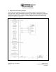
Pin - Signal Name (J101 25 Pin D-sub)
1 - Headset 1 Out H
This analog output provides the High side of the receive and sidetone audio output from
either FM-1 transceiver (Mode 2) or the summation of FM-1 and FM-2 (Mode 1).
Standard audio levels of 100 mW into 600 ohm load is provided for standard modulation
(1.0 kHz tone, 3 kHz FM Mod). This output is normally sent an audio panel. This output
must use shielded wire.
2 - Headset 1 Out L
This analog output provides the Low side of the receive and sidetone audio output from a
transceiver. Normally this output is either grounded or sent to an audio panel. This
output must use shielded wire.
3 - CAN Data H
This bi-directional pin provides for data communications between a C-2000 and P-2000
or RT-2000. Voltage levels range between 0 and 5 VDC. This pin is only used when a
system incorporates a C-2000. Twisted Shielded wire should be used with this pin.
4 - CAN Data L
This bi-directional pin provides for data communications between a C-2000 and P-2000
or RT-2000. Voltage levels range between 0 and 5 VDC. This pin is only used when a
system incorporates a C-2000. Twisted Shielded wire should be used with this pin.
5 - External Speaker Out
This analog audio output is the summation of the receive audio of either or both
transceiver modules. It does not output sidetone. Normally this audio is provided for
special applications where a speaker rather than Headset is used. It can drive a 10K
load with .9 VRMS. This output is intended to drive a powered speaker. Use shielded
wire.
6 - External Speaker Return
This pin provides the ground path for the external speaker output. Use shielded wire.
7 - PTT 1 Input
This input when grounded activates the transmitter for FM - 1 or FM - 2 (Depending on
operating mode and selected transceiver). Normally this is connected to the audio panel
PTT output. If a discreet microphone is being used (no audio panel) this pin should be
tied to Mic 1 Input L.