
User's Manual


P-2000/C-2000/RT-2000
INSTALLATION MANUAL
Publication No. 150-049106 Page 35 of 41
Rev. A P-2000 Installation Manual
Oct 2003
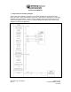
17 - 5 VDC/5 VRMS Panel lite
This pin provides for 5 VDC or 5 VRMS aircraft lite dimmer buss control of the keyboard
lighting (the LCD brightness is set by the user via keypad input). This pin does not draw
power from the buss but simply monitors the voltage for proper lite tracking. Either 28 V
or 5 volt may be used but not at the same time. This function is not used on the RT-
2000 so no connection is required.
18 - Reserved Spare #2
This reserved for future use.
19 - 28 VDC Aircraft Power
This pin provides 28 VDC aircraft power to the unit. Loading requirements and proper
circuit breaker choices are P-2000: 4 amps, RT-2000: 4 amps, C-2000: 2 amps.
20 - 28 VDC Aircraft Ground
This pin provides the ground return for the 28 VDC aircraft power to the unit.
21 - PTT 2 Input
This input when grounded activates the transmitter for FM - 2. Normally this is connected
to the audio panel PTT output. If a discreet microphone is being used (no audio panel)
this pin should be tied to Mic 2 Input L.
22 - Reserved Spare #3
This reserved for future use.
23 - Mic 2 Input H
This pin is the high side of a differential microphone 2 input and provides a 150 ohm input
impedance for the crew microphone input. Normally this pin is connected to the audio
panel. Carbon microphone DC bias is provided by the unit. Standard input of 1kHz tone
@ .25VRMS should produce standard FM modulation out (3.0 kHz). Use shielded wire.
24 - Mic 2 Input L
This pin is the low side of a differential microphone 2 input. Normally this pin is
connected to the audio panel. Use shielded wire.
25 - Reserved Spare #4
This reserved for future use.