
Installation Manual


P-2000/C-2000/RT-2000
Installation Manual
Page 36 of 41 Publication No. 150-049106
P-2000 Installation Manual Rev. A
Oct 2003
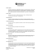
J102 15 Pin D-Sub
Pin SIGNAL NAME
1 External RS232 TX
2 External RS232 RX
3 RS232 Select 1
4 RS232 Select 2
5 ISP Start Discrete
6 Normalized Audio 1 Out H
7 Reserved Spare #5
8 Normalized Audio 2 Out H
9 Reserved Spare #6
10 Ground
11 Reserved Spare #1
12 Reserved Spare #2
13 Reserved Spare #3
14 Reserved Spare #4
15 Ground
Table 3.2 J102 Pin Numbers and Signal Names
Pin - Signal Name
1 - External RS232TX
This pin is a digital output from the unit. It provides for data communication during software flash
procedures.
2 - External RS232RX
This pin is a digital input to the unit. It provides for data communication during software flash
procedures.
3 - RS232 Select 1
4 - RS232 Select 2
This pins select which internal module receive the RS232 data being transferred on pins 1 and 2
of J102. The choices for these pins are listed in the table below:
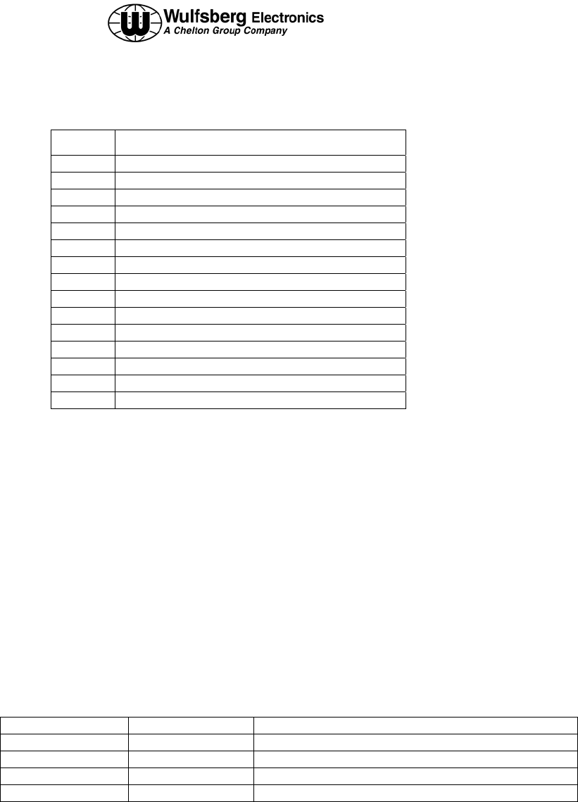
Pin 3 Pin 4 Selection
N/C N/C TBD
Ground N/C TBD
N/C Ground TBD
Ground Ground TBD
5 - ISP Start Discrete
This pin is used only during Flash software loading during maintenance.