P-2000/C-2000/RT-2000 OPERATOR’S MANUAL P-2000 and C-2000/RT-2000 Transceiver Systems P-2000 Part Number: 400-049200-11-xxx-xxxx-xxxx Software Version: 1, Mod 4 C-2000 Part Number 400-049300-11-xxx Software Version: 1, Mod 4 RT-2000 Part Number 400-049400-11-xxx-xxxx-xxxx Software Version: 1, Mod 4 Publication No. 150-049105 Rev.
P-2000/C-2000/RT-2000 OPERATOR’S MANUAL TABLE OF CONTENTS INTRODUCTION .......................................................................................................................................................6 FEATURES ..................................................................................................................................................................6 TRANSCEIVER OVERVIEW ..............................................................................................
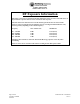
P-2000/C-2000/RT-2000 OPERATOR’S MANUAL RF Exposure Information This radio is restricted to occupational/controlled applications where users have been made aware of the potential for exposure and can exercise control over their exposure. Antennas used for the radio must not exceed the antenna gain shown below for each transmit frequency range. The antenna must be installed at least or exceeding the minimum distance away from any person(s) depending on the transmit frequency.
P-2000/C-2000/RT-2000 OPERATOR’S MANUAL IMPORTANT MOTOROLA CPS PROGRAMMING NOTES The following items must be performed or the P-2000 will not function properly! 1. Zones must be set for a maximum of 16 channels per zone. 2. Do not use scan on any personality. 3. Do not change the button settings or menu items. Leave them to the factory defaults. 4. Disable all messages such as display encryption key name on mode change. 5.
P-2000/C-2000/RT-2000 OPERATOR’S MANUAL Introduction The Wulfsberg "2000" family of Flexcomm products are comprised of the P-2000 panel mount transceiver and the RT-2000 remote mount transceiver which is controlled by the C-2000 control head.
P-2000/C-2000/RT-2000 OPERATOR’S MANUAL Transceiver Overview The Wulfsberg 2000 family of radio products are FM Tactical transceivers that incorporate one or two transceiver modules and control functions into a single panel mount unit (P-2000) or a panel mount control head (C-2000) and remote mount RT-2000 Transceiver. Part number variations of the unit exist for any combination of the following frequency bands: 137-174 MHz, 403-470 MHz or 380-470 MHz, 450-520 MHz, and 806-870 MHz or 764-870 MHz.
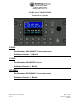
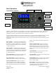
P-2000/C-2000/RT-2000 OPERATOR’S MANUAL Basic Operations Front Panel & Controls FM #1 Select FM #1 Transfer FM #2 Transfer FM #1 Volume Data Port FM #2 Select FM #2 Volume Keypad Cursor Knob Value/Enter/Pwr Knob DISPLAY - The P-2000 has a color LCD display. It provides the visual feedback for the system. Exactly what is displayed depends on the current operating mode of the P-2000. During normal operation, the top area shows information for FM #1 and the bottom line shows information for FM #2.
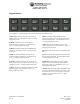
P-2000/C-2000/RT-2000 OPERATOR’S MANUAL Keypad Buttons The P-2000 has a 12 button keypad. Each button’s functions are described below. 1:DIR Toggles the active transceiver in and out of DIRECT mode. Use this button to enter a “1” during keypad entry mode. 2:MODE This button will cycle through the enhanced modes of operation. Use this button to enter a “2” during keypad entry mode. 6:KEY This button will prompt the user for a transmit encryption key to override the preset value for the active transceiver.
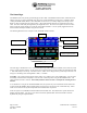
P-2000/C-2000/RT-2000 OPERATOR’S MANUAL The Home Page The HOME PAGE is the primary operational page of the P-2000. The HOME PAGE becomes visible when the P2000 is ready for user input, immediately after the power up and initialization sequences have completed. When viewing the HOME PAGE, Radio 1 (Also called FM1 or transceiver #1) is always displayed on the top section. Radio 2 is always displayed on the bottom section. All keypad-initiated operations are performed on the active radio.
P-2000/C-2000/RT-2000 OPERATOR’S MANUAL STATUS LINE - The status line is located on the very bottom of the display and it is where the user will be prompted to either input more information via the keypad, or where the Message Indictor will show there is a system message to view. In this case the user should push the MSG button to show the Message page. Discreet Indicators – The following discreet indicators apply to both FM1 and FM2.
P-2000/C-2000/RT-2000 OPERATOR’S MANUAL Turning the System On and Off To power-on the P-2000, press and hold the PWR button (push in the VALUE Knob) for approximately one second and release. Several version number and copyright pages appear on the display while the unit performs a self-test and initializes the attached radio systems. When initialization is complete, the HOME PAGE will appear on the display. (-XX = latest software mod) To power the P-2000 OFF, press and hold the PWR button for 3 seconds.
P-2000/C-2000/RT-2000 OPERATOR’S MANUAL Setting the Display Brightness When the user presses the DIM button, the display brightness adjustment display appears. When the value knob is turned clockwise, the display brightness increases in intensity. When the value knob is turned counter clockwise, the display brightness decreases in intensity. The Brightness display disappears when no value knob activity has been present for more than 2 seconds.
P-2000/C-2000/RT-2000 OPERATOR’S MANUAL Selecting the Active Transceiver To make FM1 or FM2 the “active transceiver” means that the keypad/rotary knobs will perform operations on that transceiver. The active transceiver is always highlighted in a bright blue color. As shown in the picture below, FM1 is the active transceiver. FM #1 Select To make FM1 the active transceiver, push the FM #1 SELECT BUTTON as shown above.
P-2000/C-2000/RT-2000 OPERATOR’S MANUAL Selecting a Standby Channel Using the Cursor/Value Knob When the P-2000 first powers on, the selected channels will be set to those that were active when the unit was powered down. To select a different preset channel, do the following: Using the cursor knob, put the square cursor around the channel number. Turn the value knob until the channel is your desired channel. If you wish to make this your active channel, push the transfer button.
P-2000/C-2000/RT-2000 OPERATOR’S MANUAL Selecting a Channel by Alphanumeric Identifier To change the standby channel using the alpha identifier, use the cursor knob to move the cursor square around the alpha identifier as shown below. Turn the value knob until the channel is your desired channel. Notice that channels change alphabetically. Using the Direct/Repeat Feature The P-2000 supports both direct and repeat modes of operation.
P-2000/C-2000/RT-2000 OPERATOR’S MANUAL Receiving/Transmitting Transmitting To transmit on a radio system, select the appropriate source on your audio panel, and key the microphone. Transmission will begin on the radio’s currently selected Active channel. During the transmission, the radio’s transmit indicator will light, and the channel’s transmit frequency will be displayed. The following illustration depicts FM #1 transmitting. Receiving The P-2000 is constantly monitoring its radios for reception.
P-2000/C-2000/RT-2000 OPERATOR’S MANUAL QMEM Operations When the user presses the QMEM key, the system will enter the QMEM mode. This mode allows the user to either select or program a QMEM location. When the user presses the QMEM key, then presses a keypad key (0-9), the channel programmed into the corresponding (0-9) QMEM location shall be loaded into the active channel, and the previously active channel shall be loaded into the standby channel.
P-2000/C-2000/RT-2000 OPERATOR’S MANUAL MESSAGE PAGE This page allows the user to manage text messages for the system. When no unread messages exists within the system, the MSG indicator will not be visible on the normal operation page. When the MSG key is pressed on the normal operation page and no messages are available, the no message page is displayed. This page is depicted below. The only selectable item on this page shall be the back button. Pressing ENTER will return to the HOME page.
P-2000/C-2000/RT-2000 OPERATOR’S MANUAL The cursor knob allows the selection of the message list, back button, erase button, and next button. Pressing ENTER while the back button is selected returns to the previous page. Pressing ENTER while the erase button is selected deletes the currently selected message from the message list. Pressing ENTER while the next button is selected invokes the message view page for the currently selected message in the message list.
P-2000/C-2000/RT-2000 OPERATOR’S MANUAL Programming/Editing a Preset Channel The EDIT PAGE allows the operator to temporarily change properties of a preset channel. Precisely which properties can be changed varies with channel and radio type At a minimum, all information that can be determined by the system during the LEARN mode is displayed on this page. While on the HOME page press the PROG button and Programming Mode display page will be seen.
P-2000/C-2000/RT-2000 OPERATOR’S MANUAL Frequency Fields (FRQ:) – These fields display the current channel’s receive and transmit frequencies. Tone Fields (TN:) – These fields display the current channel’s transmit and receive CTCSS/DCS (PL/DPL) tones. NAC Code Fields (NAC:) – These fields display the current channel’s transmit and receive NAC codes used on P-25 systems. Type Fields (Type:) – This field displays whether the channel is Analog, Digital, or Mixed (Analog and Digital).
P-2000/C-2000/RT-2000 OPERATOR’S MANUAL Enhanced System Features Relay Mode Relay Mode allows your aircraft’s P-2000-based transceiver system to automatically relay receiver audio from one transceiver and retransmit it out the opposite transmitter. If a Relay Mode link is established between two locations, a message received from one location is automatically retransmitted to the other. You can establish relay operation as follows. • From the HOME page select the desired channel for FM1.
P-2000/C-2000/RT-2000 OPERATOR’S MANUAL Simulcast Mode Simulcast Mode allows you to transmit simultaneously to two locations that have radios tuned to different frequencies. You can establish simulcast operation as follows. • From the HOME page select the desired channel for FM1. • From the HOME page select the desired channel for FM2. • Press the MODE button and the Mode Selection page will be displayed: • Select the SIMULCAST MODE by high-lighting the option and pressing the ENTER button.
P-2000/C-2000/RT-2000 OPERATOR’S MANUAL Relay/Simulcast Mode Relay-Simulcast mode combines the functions of Relay Mode and Simulcast Mode. It allows you to establish an automatic radio link with two other locations that have radios tuned to different frequencies in different frequency bands, and allows you to transmit to those same locations simultaneously. You can establish relay/simulcast operation as follows. • From the HOME page select the desired channel for FM1.
P-2000/C-2000/RT-2000 OPERATOR’S MANUAL Repeater Mode Repeater mode is not a specific mode of the P-2000 but an airborne repeater can effectively be created by preprogramming specific channels and then using the RELAY MODE. It is also necessary for the two transceivers, FM1 and FM2 to use the same band. In other words, you cannot perform a repeater function with a P-2000 that has FM1 operating in the 137-174 MHz band and FM2 operating in the 800 MHz band.
P-2000/C-2000/RT-2000 OPERATOR’S MANUAL Encryption Features Turning Encryption On and Off Select FM1 or FM2 depending on which transceiver you what to encrypt. Press the PVT button to toggle encryption on and off. If the P-2000 preset channel being used has been set up for encryption, the privacy indicator will light. PVT Indicator NOTE: Encryption can only be turned on for channels that have been pre-programmed with an encryption key.
P-2000/C-2000/RT-2000 OPERATOR’S MANUAL • Press the ENTER button to accept the displayed key. The display will return to the HOME PAGE. • When transmitting, and if encryption keys are properly loaded, a tone at the start of the transmission will be generated by the radio and heard by the operator. Begin speaking AFTER the tone or part of your transmission will be lost.
P-2000/C-2000/RT-2000 OPERATOR’S MANUAL The following illustrates the display with an OTAR in progress. NOTE: The OTAR process will automatically time-out after 2 minutes of unsuccessful OTAR attempts. At anytime during the OTAR operation, or after the OTAR has completed, whether successfully or unsuccessfully, the user must press the OTAR or HOME key to cancel/exit the OTAR operation. Doing so shall display the OTAR cancel confirmation page, as depicted below.
P-2000/C-2000/RT-2000 OPERATOR’S MANUAL Loading Encryption Keys Before a transceiver will transmit encrypted messages, the user must load encryption keys into the transceiver. To accomplish this, the user must first put the transceiver into KEY LOAD mode, and then using a Motorola KVL, load the keys. Perform the following steps to load keys: • From the HOME page press the PROG button.
P-2000/C-2000/RT-2000 OPERATOR’S MANUAL Erasing Encryption Keys With A Key loader It may be desirable to erase the encryption keys contained in a P-2000 transceiver. For example, prior to sending the unit in for service. This can be accomplished as follows. • Ensure you are on the HOME PAGE, and the cursor is on an encryption capable channel. • Press the PROG button.
P-2000/C-2000/RT-2000 OPERATOR’S MANUAL CPS MODE Loading Channel Memory Programming the preset channels of the P-2000 must be performed with PC based program available from MOTOROLA named CPS. Normally this procedure is accomplished by a technician familiar with this software package since extensive knowledge is required to operate the Motorola software. As a note to the technician, no RIB box is required between the PC and P-2000 since Wulfsberg has built this capability into its transceiver.
P-2000/C-2000/RT-2000 OPERATOR’S MANUAL The process to read and modify the transceiver preset channels is as follows: • Ensure you are on the HOME PAGE. • Press the PROG button. If prompted, enter the password #1 (In the system programming, the user has the option of eliminating this password by setting it to “0000”). The PROGAM page will be displayed as below: • Highlight the CPS option and press the enter button.
P-2000/C-2000/RT-2000 OPERATOR’S MANUAL • Press the HOME button once to end the CPS Load process, this will cause the system to briefly display a “System busy, please wait…” dialog, and will then prompt the user to enter LEARN MODE. In this mode, the P-2000 computer interrogates the internal transceivers to determine what changes have been made and to update its internal memory. This process can take several minutes. The operator will be shown progress as the system completes its task.
P-2000/C-2000/RT-2000 OPERATOR’S MANUAL SYSTEM SETUP MODE The P-2000 comes from the factory already configured for a normal installation, however, there are several options the installer can select. These options are very simple to update. The process is as follows. Ensure you are on the HOME PAGE and press the PROG button. • Highlight the SYSTEM option and press the ENTER button. You will be prompted to enter password #3.
P-2000/C-2000/RT-2000 OPERATOR’S MANUAL • • The second setup page allow the selection of the following • Enable Standby – the active/standby channel operation can be set to active only by saying “YES” to this option. A “NO” will eliminate the standby channel and the user will tune active channels only. Factory default for this option is “YES”. • Lock QMEM – To keep users from altering the QMEM settings, this option can be set to YES. Factory default for this option is “NO”.
P-2000/C-2000/RT-2000 OPERATOR’S MANUAL MAINTENANCE PAGES The following information is not normally needed by and operator. The maintenance pages are used by a technician to make audio level adjustments and verify system operation via BITE (Built-In-Test). • Ensure you are on the HOME PAGE and press the PROG button. • Highlight the MAINTENANCE (It’s located below the SYTEM option) option and press the ENTER button. You will be prompted to enter the Password #2.
P-2000/C-2000/RT-2000 OPERATOR’S MANUAL Flashport Mode The flashport mode is one of the mode options available on the Transceiver Maintenance page. This mode allows the technician to upgrade the embedded software within the internal transceiver. • Select the transceiver to perform the flash upgrade. Highlight START and press enter to begin. Perform the flash upgrade. Data mode, WED service mode and extended protocol modes are accessed using the same procedure.
P-2000/C-2000/RT-2000 OPERATOR’S MANUAL Software Versions Display Page To view the software version of all programmed parts within the P-2000, select the Software Version page from the MAINTENANCE MODE page. • From the MAINTENANCE MODE page, Highlight the SOFTWARE VERSIONS option and press ENTER. This page shall allow the user to view the part numbers and/or version numbers of the software modules installed in the P-2000 radio system.
P-2000/C-2000/RT-2000 OPERATOR’S MANUAL Steps to Successful Setup and Operation While we would like to pull products out of the box and immediately start to use them, this system is one that takes just little work to get to that point. First READ THE OPERATORS MANUAL!!!! This will familiarize you with the buttons and display pages of the system. The following checklist will help installers setup the P-2000 or C2000/RT-2000. 1. Note all part numbers of components in your system..