
User's Manual


P-2000/C-2000/RT-2000
OPERATOR’S MANUAL
Page 8 of 40 Publication No. 150-049105
Operator’s Manual Rev. C
Jul 2005
Basic Operations
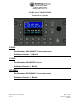
Front Panel & Controls
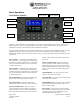
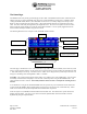
DISPLAY - The P-2000 has a color LCD display. It provides the visual feedback for the system. Exactly what is
displayed depends on the current operating mode of the P-2000. During normal operation, the top area shows
information for FM #1 and the bottom line shows information for FM #2.
The keypad and cursor/value rotary knobs perform functions on the transceiver that is highlighted in blue. The blue
highlight also indicates which transceiver has been selected for transmitting when the system is operating in
SINGLE MIC MODE. This is the mode where there is only one audio panel position being shared between the two
transceivers.
FM #1 SELECT – This button selects FM #1 as the
active transceiver. This is depicted on the display by
the FM1 area turning a bright blue color. The keypad
and cursor/value knobs will now operate exclusively
on the FM1 transceiver.
FM #2 SELECT - This button selects FM #2 as the
active transceiver. This is depicted on the display by
the FM2 area turning a bright blue color. The keypad
and cursor/value knobs will now operate exclusively
on the FM2 transceiver.
FM #1 TRANSFER – The button will transfer (Flip-
flop) the active and standby channels for FM1.
FM #2 TRANSFER – This button will transfer
(Flip-flop) the active and standby channels for FM2.
FM #1 VOLUME KNOB – This rotary switch is
used to control the volume of FM #1. Pressing the
button will perform a “Test” of the audio system by
allowing audio from that transceiver to be sent to the
headset. This is used to vary volume levels of that
transceiver.
FM #2 VOLUME KNOB – This rotary switch is
used to control the volume of FM #2. Pressing the
button will perform a “Test” of the audio system by
allowing audio from that transceiver to be sent to the
headset. This is used to vary volume levels of that
transceiver.
CURSOR KNOB – This rotary switch is used to
move the cursor around the display.
VALUE KNOB – This rotary knob is used to modify
values at the cursor position.
ENTER/PWR button – Pushing the VALUE KNOB
(Small rotary knob) button performs “Enter” and
power on/off operations.
DATA PORT – This connector is used to transfer
data between the P-2000 and Encryption Key loaders
or for loading preset channel information via the
Motorola CPS software (PC based).
FM #1 Select
FM #2 Select
FM #1 Volume
FM #2 Volume
Data Port
Cursor Knob
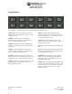
Keypad
FM #1 Transfer FM #2 Transfer
Value/Enter/Pwr
Kn
ob