
Data Sheet

Data Sheet
©2013
Würth Elektronik eiSos GmbH & Co. KG - REV 0.2
PRELIMINARY
13/ 25
171012401/WPMDH1102401J
MagI³C Power Module Product Family
VDRM - Variable Step Down Regulator Module
J CIRCUIT DESCRIPTION
(10)
The selection of R
ON
and f
SW(CCM)
must be confined by limitations in the on-time and off-time for the COT control
section. The on-time of the MagI³C power module timer is determined by the resistor R
ON
and the input voltage V
IN
. It
is calculated as follows:
(11)
The inverse relationship of t
ON
and V
IN
gives a nearly constant switching frequency as V
IN
is varied. R
ON
should be
selected such that the on-time at maximum V
IN
is greater than 150ns. The on-timer has a limiter to ensure a minimum
of 150ns for t
ON
. This limits the maximum operating frequency, which is governed by the following equation:
(12)
This equation can be used to select R
ON
if a certain operating frequency is desired so long as the minimum on-time of
150ns is observed. The limit for R
ON
can be calculated as follows:
(13)
If R
ON
calculated in equation (10) is less than the minimum value determined in equation (13) a lower frequency
should be selected. Alternatively, V
IN(MAX)
can also be limited in order to keep the frequency unchanged.
Additionally note, the minimum off-time of 260ns limits the maximum duty ratio. Larger R
ON
(lower f
SW
) should be
selected in any application requiring large duty ratio.
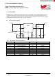
Discontinuous Conduction and Continuous Conduction Modes
At light load the regulator will operate in discontinuous conduction mode (DCM). With load currents above the critical
conduction point, it will operate in continuous conduction mode (CCM). When operating in DCM the switching cycle
begins at zero amps inductor current; increases up to a peak value, and then recedes back to zero before the end of
the off-time. Note that during the period of time that inductor current is zero, all load current is supplied by the output
capacitor. The next on-time period starts when the voltage on the FB pin falls below the internal reference. The
switching frequency is lower in DCM and varies more with load current as compared to CCM. Conversion efficiency in
DCM is maintained since conduction and switching losses are reduced with the smaller load and lower switching
frequency. Operating frequency in DCM can be calculated as follows:
(14)
In CCM, current flows through the inductor through the entire switching cycle and never falls to zero during the off-
time. The switching frequency remains relatively constant with load current and line voltage variations. The CCM
operating frequency can be calculated using equation (12) above. The approximate formula for determining the
DCM/CCM boundary is as follows:
(15)
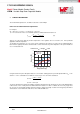
The inductor internal to the module is 15μH. This value was chosen as a good balance between low and high input
voltage applications. The main parameter affected by the inductor is the amplitude of the inductor ripple current (I
LR
).
I
LR
can be calculated with:
(16)
Where V
IN
is the maximum input voltage and f
SW
is determined from equation (10).
If the output current I
OUT
is determined by assuming that I
OUT
= I
L
, the higher and lower peak of I
LR
can be determined.
Be aware that the lower peak of I
LR
must be positive if CCM operation is required.
Step 7. Select Feed Forward Capacitor (Cff)
As worst case, assume the gain of A
FB
with the C
FF
capacitor at the switching frequency is 1. The selected capacitor
should have sufficient voltage and RMS current rating.