
Data Sheet

Data Sheet
©2013
Würth Elektronik eiSos GmbH & Co. KG - REV 0.2
PRELIMINARY
11/ 25
171050601/WPMDM1500602J
MagI³C Power Module Product Family
VDRM - Variable Step Down Regulator Module
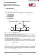
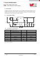
J CIRCUIT DESCRIPTION
MagI³C 7 Steps to design the power application
The next 7 simple steps will show how to select the external components to design your power application:
1. Program under voltage lockout
2. Program output voltage
3. Select soft-start capacitor
4. Tracking supply option
5. Select output capacitor
6. Select input capacitor
7. Synchronisation option
C
IN
V
IN
SYNC
VIN
EN AGND FB
SS/TRK
VOUT
Module
R
ENT
R
ENB
R
FBT
R
FBB
C
OUT
V
OUT
C
SS
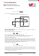
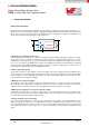
Step 1. Select Enable Divider, R
ENT
, R
ENB
and R
ENH
Internal to the module is a 2MΩ pull-up resistor connected from V
IN
to Enable. For applications not requiring precision
under voltage lock out (UVLO), the Enable input may be left open circuit and the internal resistor will always enable
the module. In such case, the internal UVLO occurs typically at 4.3V (V
IN rising
).
In applications with separate supervisory circuits Enable can be directly interfaced to a logic source. In the case of
sequencing supplies, the divider is connected to a rail that becomes active earlier in the power-up cycle than the
MagI³C power module output rail. Enable provides a precise 1.279V threshold to allow direct logic drive or connection
to a voltage divider from a higher enable voltage such as V
IN
. Additionally there is 21μA (typ) of switched offset
current allowing programmable hysteresis. See Figure 1.
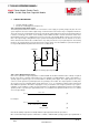
The function of the enable divider is to allow the designer to choose an input voltage below which the circuit will be
disabled. This implements the feature of programmable UVLO. The two resistors should be chosen based on the
following ratio:
(1)
The MagI³C power module typical application shows 12.7kΩ for R
ENB
and 42.2kΩ for R
ENT
resulting in a rising UVLO
of 5.46V. Note that this divider presents 8.33V to the input when the divider is raised to 36V which would exceed the
recommended 5.5V limit for Enable. A midpoint 5.1V zener clamp is applied to allow the application to cover the full
6V to 36V range of operation. The zener clamp is not required if the target application prohibits the maximum Enable
input voltage from being exceeded. Additional enable voltage hysteresis can be added with the inclusion of R
ENH
. It is
possible to select values for R
ENT
and R
ENB
such that R
ENH
is a value of zero allowing it to be omitted from the design.
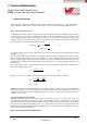
Rising threshold can be calculated as follows:
1.
2.
3.
4.
5.
6.
7.