
Data Sheet

Data Sheet
©2013
Würth Elektronik eiSos GmbH & Co. KG - REV 0.2
PRELIMINARY
13/ 25
171050601/WPMDM1500602J
MagI³C Power Module Product Family
VDRM - Variable Step Down Regulator Module
J CIRCUIT DESCRIPTION
Thermal shutdown condition
Internal V
CC
UVLO (Approx 4.3V input to V
IN
)
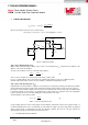
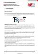
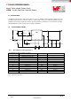
Step 4. Tracking Supply divider option
The tracking function allows the module to be connected as a slave supply to a primary voltage rail (often the 3.3V
system rail) where the slave module output voltage is lower than that of the master. Proper configuration allows the
slave rail to power up coincident with the master rail such that the voltage difference between the rails during ramp-up
is small (i.e.<0.15V typ). The values for the tracking resistive divider should be selected such that the effect of the
internal 50uA current source is minimized. In most cases the ratio of the tracking divider resistors is the same as the
ratio of the output voltage setting divider. Proper operation in tracking mode dictates the soft-start time of the slave
rail be shorter than the master rail; a condition that is easy satisfy since the C
SS
cap is replaced by R
TKB
. The tracking
function is only supported for the power up interval of the master supply; once the SS/TRK rises past 0.8V the input is
no longer enabled and the 50 µA internal current source is switched off.
SS/TRK
INT VCC
50µA
5V V
OUT
R
fbt
2.26k
R
fbb
1.07k
FB
3.3V Master
R
tkt
226k
R
tkb
107k
Figure 2. Tracking option input detail
Step 5. Select Output Capacitor (C
OUT
)
None of the required C
OUT
output capacitance is contained within the module. A minimum value of 200 μF is required
based on the values of internal compensation in the error amplifier. Low ESR tantalum, organic semiconductor or
specialty polymer capacitor types are recommended for obtaining lowest ripple. The output capacitor C
OUT
may
consist of several capacitors in parallel placed in close proximity to the module. The output capacitor assembly must
also meet the worst case minimum ripple current rating of 0.5 * I
LR P-P
, as calculated in equation (14) below. Beyond
that, additional capacitance will reduce output ripple so long as the ESR is low enough to permit it. Loop response
verification is also valuable to confirm closed loop behavior. For applications with dynamic load steps; the following
equation provides a good first pass approximation of C
OUT
for load transient requirements. Where V
OUT-Train
is 100mV
on a 3.3V output design.
(4)
For example:
(5)
(6)
Note that the stability requirement for 200μF minimum output capacitance will take precedence.
One recommended output capacitor combination is a 220uF, 7 milliohm ESR specialty polymer cap in parallel with a