
Data Sheet

Data Sheet
©2013
Würth Elektronik eiSos GmbH & Co. KG - REV 0.2
PRELIMINARY
14/ 25
171050601/WPMDM1500602J
MagI³C Power Module Product Family
VDRM - Variable Step Down Regulator Module
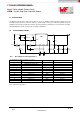
J CIRCUIT DESCRIPTION
100µF 6.3V X5R ceramic. This combination provides excellent performance that may exceed the requirements of
certain applications. Additionally some small ceramic capacitors can be used for high frequency EMI suppression.
Step 6. Select Input Capacitor (C
IN
)
The MagI³C power module contains a small amount of internal ceramic input capacitors. Additional input capacitance
is required external to the module to handle the input ripple current of the application. The input capacitor can be
several capacitors in parallel. This input capacitance should be located in very close proximity to the module. Input
capacitor selection is generally directed to satisfy the input ripple current requirements rather than by capacitance
value. Input ripple current rating is dictated by the equation:
(8)
where
(As a point of reference, the worst case ripple current will occur when the module is presented with full load current
and when V
IN
= 2 * V
OUT
).
Recommended minimum input capacitance is 22µF X7R (or X5R) ceramic with a voltage rating at least 25% higher
than the maximum applied input voltage for the application. It is also recommended that attention be paid to the
voltage and temperature derating of the capacitor selected. It should be noted that ripple current rating of ceramic
capacitors may be missing from the capacitor data sheet and you may have to contact the capacitor manufacturer for
this parameter.
If the system design requires a certain minimum value of peak-to-peak input ripple voltage (ΔV
IN
) be maintained then
the following equation may be used.
(9)
If ΔV
IN
is 1% of V
IN
for a 12V input to 3.3V output application this equals 120 mV and f
SW
= 812kHz.
Additional bulk capacitance with higher ESR may be required to damp any resonant effects of the input capacitance
and parasitic inductance of the incoming supply lines. The MagI³C power module typical applications schematic and
evaluation board include a 150μF 50V aluminum capacitor for this function. There are many situations where this
capacitor is not necessary.
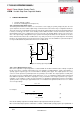
Step 7. Synchronisation option (SYNC)
The PWM switching frequency can be synchronized to an external frequency source. If this feature is not used,
connect this input either directly to ground, or connect to ground through a resistor of 1.5kΩ ohm or less. The allowed
synchronization frequency range is 650kHz to 950 kHz. The typical input threshold is 1.4V transition level. Ideally the
input clock should overdrive the threshold by a factor of 2, so direct drive from 3.3V logic via a 1.5kΩ Thevenin source
resistance is recommended. Note that applying a sustained “logic 1” corresponds to zero hertz PWM frequency and
will cause the module to stop switching.
Power loss and board thermal requirements