
Data Sheet

Data Sheet
©2013
Würth Elektronik eiSos GmbH & Co. KG - REV 0.2
PRELIMINARY
18/ 25
171050601/WPMDM1500602J
MagI³C Power Module Product Family
VDRM - Variable Step Down Regulator Module
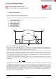
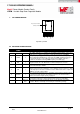
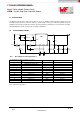
L PIN CONFIGURATION
SYNC
VIN
EN
AGND
FB
SS/TRK
VOUT
1 2 3 4 5
6
7
6 7
Exposed Pad = PGND
Connect to AGND
Top View 7 pin PFM
M DETAILED PIN DESCRIPTION
PIN #
PIN
SYMBOL
TYPE
PIN DESCRIPTION
1
V
IN
PWR
The supply input pin is a terminal for unregulated input voltage source. It is
required to use a filtering capacitance nearby input voltage pin and PGND.
2
SYNC
I
The Sync Input pin apply a CMOS logic level square wave whose frequency is
between 650 kHz and 950 kHz to synchronize the PWM operating frequency to
an external frequency source. When not using synchronization connect to
ground. The module free running PWM frequency is 812kHz (Typ).
3
EN
I
The enable input pin is connected to the precision enable comparator and the
rising threshold is at 1.18V. Maximum recommended input level is 6.5V.
4
AGND
PWR
The analog ground pin is for all stated voltages the reference point and must be
connected externally to PGND.
5
FB
I
The feedback pin is internally connected to the regulation amplifier, the over-
voltage and short-circuit comparators. The regulation reference point is 0.796V
at this input pin. Connect the feedback resistor divider between the output and
AGND to set up the output voltage.
6
SS/TRK
I
The Soft-Start and Tracking pin is to extend the 1.6ms internal soft-start connect
an external soft start capacitor. For tracking connect to an external resistive
divider connected to a higher priority supply rail.
7
V
OUT
O
The output voltage pin is connected to the internal inductor. For the best stability
and operation connect the output capacitor between this pin and PGND.
EP
EP
Exposed
Pad
Exposed Pad – Internally connected to pin 4. Used to dissipate heat during
operation. Must be electrically connected to pin 4 external to package.