
Data Sheet


Data Sheet
©2013
Würth Elektronik eiSos GmbH & Co. KG - REV 0.2
PRELIMINARY
4/ 25
171050601/WPMDM1500602J
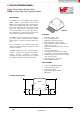
MagI³C Power Module Product Family
VDRM - Variable Step Down Regulator Module
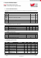
H ELECTRICAL SPECIFICATIONS
Limits are valid for recommended junction temperature range of -40°C to 125°C. Typical values represent the most likely norm at following conditions: V
IN
=12V, V
OUT
=3.3V,
T
A
=25°C, unless otherwise specified.
SYMBOL
PARAMETER
CONDITIONS
MIN
(3)
TYP
(4)
MAX
(3)
UNIT
V
IL-SYNC
Synchronization logic
zero amplitude
Relative to AGND
-
-
0.4
V
V
IH-SYNC
Synchronization logic
zero amplitude
Relative to AGND
1.5
-
-
V
SYNC
d.c.
Synchronization duty
cycle range
15
50
85
%
Maximum duty factor
-
83
-
%
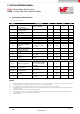
Specifications regarding to the soft-start
I
SS
SS source current
V
SS
= 0V
40
50
60
µA
tss
Internal soft-start interval
-
1.6
-
msec
Specifications regarding to the regulation and over-voltage comparator
V
FB
In-regulation feedback
voltage
V
SS
>+ 0.8V
T
J
= -40°C to 125°C
I
OUT
= 2A
0.776
0.796
0.816
V
V
FB-OVP
Feedback over-voltage
protection threshold
-
0.86
-
V
I
FB
Feedback input bias
current
-
5
-
nA
I
Q
Non Switching Input
Current
V
FB
= 0.86V
-
2.6
-
mA
I
SD
Shut Down Quiescent
Current
V
EN
= 0V
-
70
-
µA
Specifications regarding to the performance parameters
ΔV
OUT
Output Voltage Ripple
V
OUT
=3.3V, C
OUT
=220μF
w/ 7 mΩ ESR + 100µF
X7R + 2x 0.047µF BW
@ 20MHz
-
9
-
mV
PP
ΔV
OUT
/ΔV
IN
Line Regulation
V
IN
= 12V to 36V,
I
OUT
=0.001A
-
±0.02
-
%
ΔV
OÙT
/ΔI
OUT
Load Regulation
V
IN
= 12V, I
OUT
= 0.001A
to 5A
-
1
-
mV/A
η
Efficiency
V
IN
=12V, V
OUT
=3.3V,
I
OUT
=1A
-
86
-
%
η
Efficiency
V
IN
= 12V, V
OUT
= 3.3V,
I
OUT
= 5A
-
81.5
-
%
NOTES
(1)
Absolute Maximum Ratings are limits beyond which damage to the device may occur. Operating Ratings are conditions under which operation of the device is
intended to be functional. For guaranteed specifications and test conditions, see the Electrical Characteristics.
(2)
The human body model is a 100pF capacitor discharged through a 1.5 kΩ resistor into each pin. Test method is per JESD-22-114.
(3)
Min and Max limits are 100% production tested at 25°C. Limits over the operating temperature range are guaranteed through correlation using Statistical Quality
Control (SQC) methods.
(4)
Typical numbers are at 25°C and represent the most likely parametric norm.
(5)
Theta JA measured on a 3.5” x 3.5” four layer board, with three ounce copper on outer layers and two ounce copper on inner layers, sixty 10 mil thermal vias, no air
flow, and 1W power dissipation. Refer to application note layout diagrams.
(6)
JEDEC J-STD020