
Data Sheet


WPMDH1100xx1S / 173010x42
MagI
3
C Power Module
FDSM – Fixed Step Down Regulator Module
we-online.com Würth Elektronik eiSos GmbH & Co. KG – Data Sheet Rev. 1.0
© June 2016 6/24
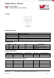
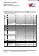
EMC BEHAVIOR
PARAMETER
TEST CONDITIONS
CLASSIFICATION
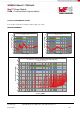
Conducted Emissions
With filter (see page 18)
Class B, according to EN55022 (see results on pages 7-8)
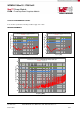
Radiated Emissions
With filter (see page 18)
Class B, according to EN55022 (see results on pages 7-8)
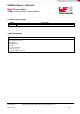
RELIABILITY
SYMBOL
PARAMETER
TEST CONDITIONS
MIN
(1)
TYP
(3)
MAX
(1)
UNIT
MTBF
Mean Time Between Failures,
according to MIL-HDBK 217F
T
A
= 25°C
8600 ·10
3
h
T
A
= 68°C
3880 ·10
3
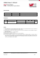
NOTES
(1) Min and Max limits are 100% production tested at 25°C. Limits over the operating temperature range are guaranteed
through correlation using Statistical Quality Control (SQC) methods.
(2) Typical numbers are valid at 25°C ambient temperature and represent statistically the utmost probability assuming the
Gaussian distribution.
(3) Depending on load current, see derating diagram
(4) Measured without heatsink, no air flow
(5) Under light load conditions the devices may not meet all specifications
(6) The industry standard for comparison of the output voltage ripple between switching regulators or modules requires a
10µF ceramic (sometimes additional 1µF ceramic in parallel) at the point of load where the voltage measurement is done
using an oscilloscope with its probe and probe jack for low voltage/high frequency (low impedance) measurement. The
oscilloscopes bandwidth is limited at 20MHz.