
User Manual


6/11
www.rohm.com
© 2016 ROHM Co., Ltd. All rights reserved.
Wireless Power Design Kit – Medium Power – 760308MP V1.0
Design Kit Manual
EUDC59-U-004 - Rev. 1.0
3.4 Transmitter (TX) Module
When power is provided to the TX Module at CONN1, LED1 will light green to indicate presence of the 19V input voltage.
Additionally LED2 will light green when the 5V DC/DC converter has started up. The Transmitter Module is now in low power “idle”
mode where it is periodically pinging on the wireless interface to detect presence of a receiver device.
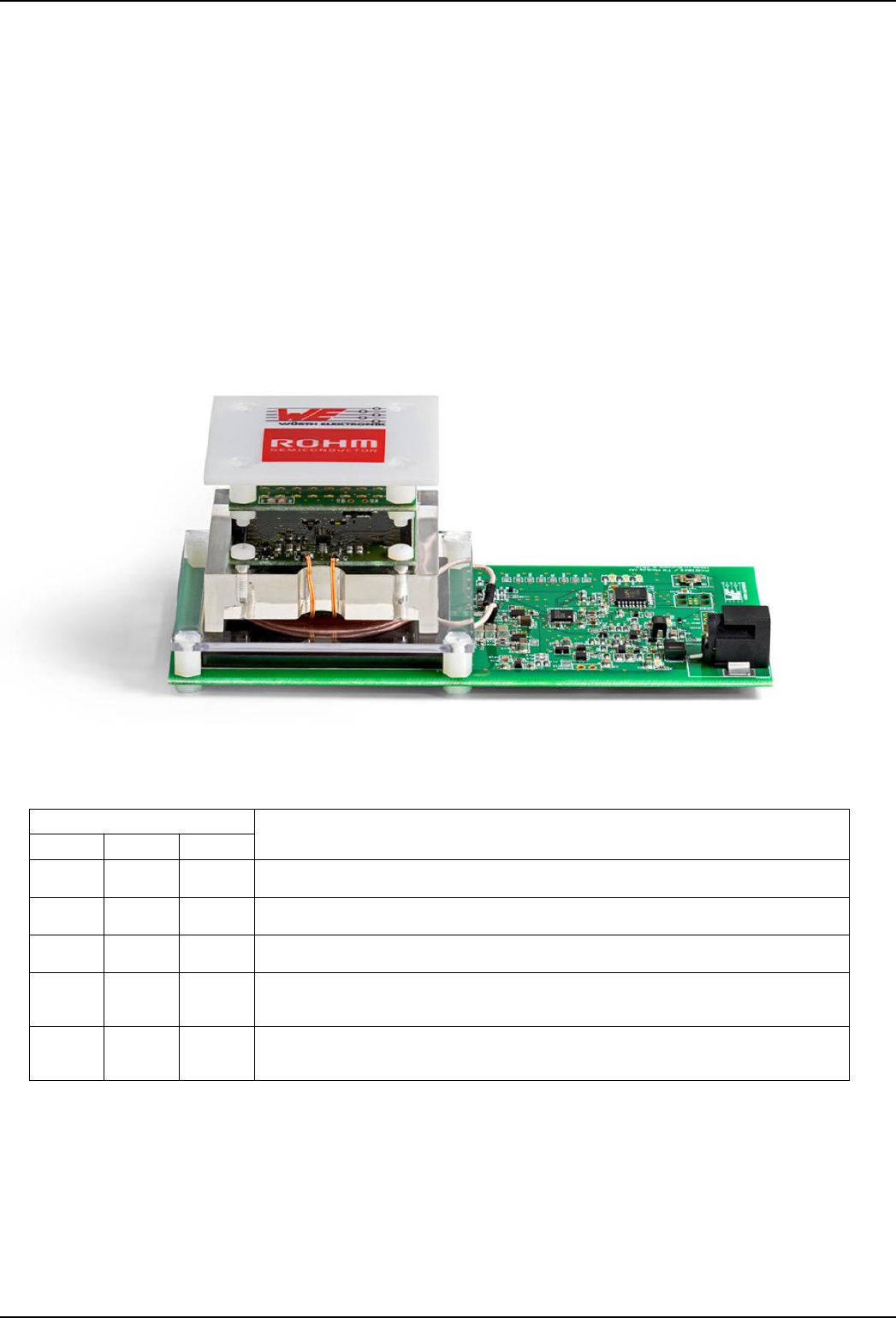
The stacked RX+LED Modules (or any other Qi compliant receiver) can now be placed anywhere on the Coil Area (as shown in
Figure 3) and the wireless power transmission will start. In low power mode (WPC baseline power profile) the LED LP will light green
to indicate successful and ongoing power transfer. In addition the LED MP will also light in medium power mode (WPC extended
power profile).
There is a red color LED FL to indicate failure modes. Slow blinking means the power transfer is still established but Field Strength
Limitation (FSL) is active. This is usually caused when the receiver has slightly moved out of alignment and safe power transfer is
not guaranteed. In this case the ROHM Receiver Module will communicate to stop power transfer if the system will not have
recovered from this failure mode within ~3s. This condition is indicated by fast blinking failure mode LED. Other reasons for stopped
power transfer can be Foreign Object Detection (FOD), Under Voltage Lockout (UVLO) or “End of Power Transfer” (EPT) requested
by the receiver. The system can only recover from this failure mode if the receiver is removed from the coil area. The transmitter will
then go to idle mode.
The different operating modes and status LED indications are summarized in Table 3. Please check
Figure 4 for the local positions of described LEDs, inputs and outputs.
Figure 3: Stacked RX+LED Module placed on coil area of TX Module
LED Name
Operating Mode Description
LP
MP
FL
Off
Off
Off
Idle mode with periodic pings for receiver detection. Very low power consumption.
On
Off
Off
LP mode (WPC baseline power profile) with up to 5W load power.
On
On
Off
MP mode (WPC extended power profile) with up to 10W (15W) load power.
On
On
or
Off
Slowly
Blinking
Power transfer is still established but Field Strength Limitation (FSL) is active. (see
above).
Off
Off
Fast
Blinking
Power transfer has been stopped due to Foreign Object Detection (FOD), EPT or
Under Voltage Lockout (UVLO). The system can only recover from this failure mode if
the receiver is removed from the coil area. The transmitter will then go to idle mode.
Table 3: Operating Modes indicated by status LEDs on the Transmitter Module