
User Manual


9/11
www.rohm.com
© 2016 ROHM Co., Ltd. All rights reserved.
Wireless Power Design Kit – Medium Power – 760308MP V1.0
Design Kit Manual
EUDC59-U-004 - Rev. 1.0
3.6 LED Load Module
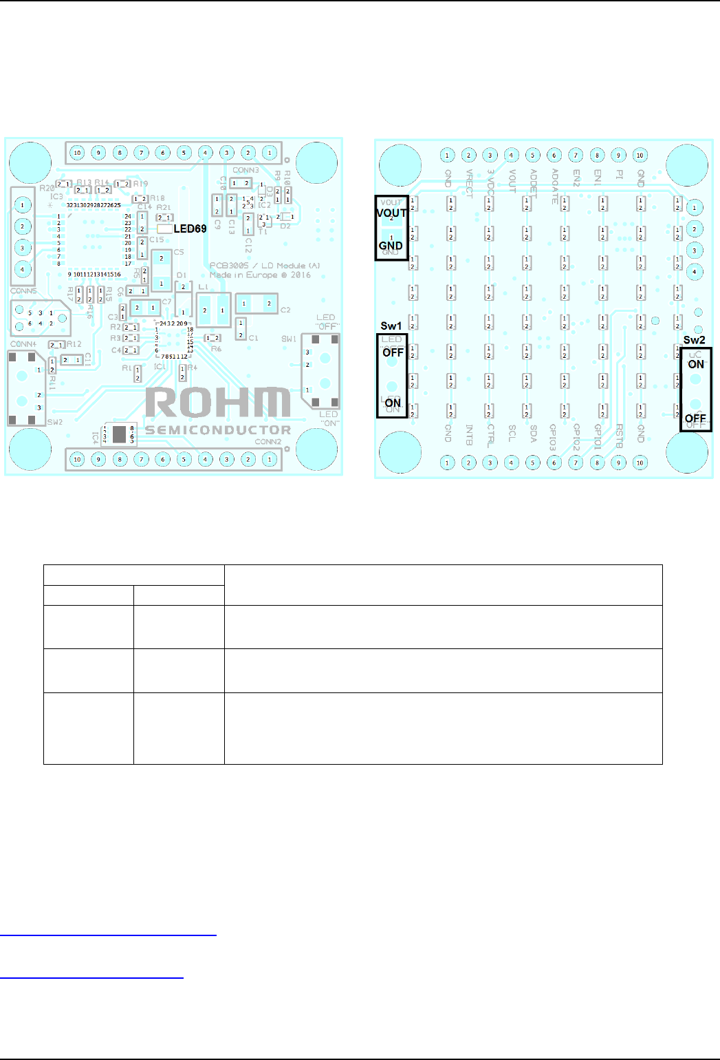
When the LED Load Module is powered by the RX Module via the VOUT pin the LED69 on the bottom side (see Figure 6) will light
white. When Sw1 is turned on (default setting) the LED driver is enabled and the LED matrix on the top side will light. Turning Sw2
off will disable the LED matrix load. In this case a user defined load may be attached between VOUT and GND as indicated in Figure
7. Please take care not to exceed the maximum specified RX load power.
Figure 6: LED Module, bottom view
Figure 7: LED Module, top view
Slide switch on LED Module
Configured Mode
Sw1: LED
1
Sw2: uC
1
On
On
Default Mode. The MCU is enabled and uses the I2C interface to configure the
RX IC BD57015 in Medium Power Mode. The LED driver is enabled, thus the
LED matrix load is lit as a demonstrative load.
Off
On
The MCU is enabled and uses the I2C interface to configure the RX IC
BD57015 in Medium Power Mode. The load to the receiver is disabled. A user
defined load may be attached to the VOUT pad on the LED Module.
Don’t care
Off
The MCU is disabled so the RX IC BD57015 works in Low Power Mode by
default. The LED loads are turned off independent from Sw1 setting. The user
may attach a custom MCU to the 2.85V supply pin and a load to the VOUT pad
of the LED module. In case the 2.85V supply is not needed the LED Module
can be removed, and the user may stack a customized MCU/load shield.
Note 1: Please change the position of these switches only when the stacked RX+LED Load Module are unpowered
Table 6: Mode configuration by slide switches of LED Module
4. Customer Support
If any further technical support is required when operating with the design kit please contact ROHM Semiconductor or Würth
Elektronik with your enquiry.
ROHM Semiconductor
wirelesspower@de.rohmeurope.com
Würth Elektronik
wirelesspower@we-online.com