User’s Guide DSL-100HNU-T1 v3 802.11n 2x2 Wireless ADSL2+ 4-port Gateway Default Login Details http://192.168.1.1 User Name: admin Password: 1234 Firmware Version 1.14 Edition 1, 12/2014 Copyright © 2014 MitraStar Technology Corp.
IMPORTANT! READ CAREFULLY BEFORE USE. KEEP THIS GUIDE FOR FUTURE REFERENCE. Graphics in this book may differ slightly from the product due to differences in operating systems, operating system versions, or if you installed updated firmware/software for your device. Every effort has been made to ensure that the information in this manual is accurate. Related Documentation • Quick Start Guide The Quick Start Guide shows how to connect the Device and get up and running right away.
Contents 9 Chapter 1: Introduction 9 Overview 9 Ways to Manage the Device 9 Good Habits for Managing the Device 10 Applications for the Device 10 Internet Access 11 Wireless Access 11 Using the WLAN/WPS Button 12 The RESET Button 12 Using the Reset Button 12 LEDs (Lights) 15 Chapter 2: Introducing the Web Configurator 15 Overview 15 Accessing the Web Configurator 17 The Web Configurator Layout 17 Title Bar 18 Main Window 19 Chapter 3: Quick Start 19 Overview 19 Quick
3 Configuring More Connections Advanced Setup 44 The 3G Backup Screen 47 WAN Technical Reference 47 Encapsulation 48 Multiplexing 48 VPI and VCI 48 IP Address Assignment 50 Chapter 6: Wireless 50 Overview 50 What You Can Do in this Chapter 50 Wireless Network Overview 52 Before You Begin 52 Wireless General Screen 54 No Security 55 Basic (Static WEP/Shared WEP Encryption) 56 More Secure (WPA2-PSK) 57 WPA2 Authentication 59 More AP Screen 60 Edit More AP 61 MAC Authent
85 The UPnP Screen 86 The IPv6 LAN Setup Screen 91 The File Sharing Screen 92 Before You Begin 94 Edit File Sharing User 95 The Printer Server Screen 95 Before You Begin 96 Technical Reference 98 Installing UPnP in Windows Example 101 Using UPnP in Windows XP Example 107 Chapter 8: Static Route 107 Overview 107 What You Can Do in this Chapter 108 Configuring Static Route 109 Add/Edit Static Route 110 IPv6 Static Route 111 IPv6 Static Route Edit 112 Chapter 9: Quality of Se
133 The ALG Screen 133 Technical Reference 133 NAT Definitions 134 What NAT Does 135 How NAT Works 136 Chapter 11: Port Binding 136 Overview 137 The Port Binding Screen 138 Port Binding Summary Screen 140 The Any Port Any Service Edit Screen 143 Chapter 12: Dynamic DNS 143 Overview 143 What You Need To Know 144 The Dynamic DNS Screen 145 Chapter 13: Filter 145 Overview 145 What You Can Do in the Filter Screens 146 The IP/MAC Filter Screen 148 The IPv6/MAC Filter Screen
169 Overview 169 The Parental Control Screen 171 Add/Edit a Parental Control Rule 173 Chapter 16: Certificates 173 Overview 173 What You Can Do in this Chapter 173 What You Need to Know 174 Verifying a Certificate 175 Local Certificates 177 Trusted CA 178 Trusted CA Import 179 View Certificate 181 Chapter 17: System Monitor 181 Overview 181 What You Can Do in this Chapter 181 What You Need To Know 182 The Log Screen 183 The WAN Traffic Status Screen 184 The LAN Traffic S
198 Chapter 23: Firmware Upgrade 198 Overview 198 The Firmware Upgrade Screen 200 Chapter 24: Backup/Restore 200 Overview 200 The Backup/Restore Screen 202 The Reboot Screen 203 Chapter 25: Remote Management 203 Overview 203 What You Can Do in the Remote Management Screens 204 What You Need to Know About Remote Management 204 The WWW Screen 205 Configuring the WWW Screen 206 Telnet Screen 207 FTP Screen 208 SNMP Screen 209 Configuring SNMP 210 DNS Screen 211 ICMP Screen
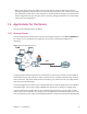
Introduction 1 Chapter Chapter 1 C H A PT ER 1 1.1 Overview The DSL-100HNU-T1 v3 is an ADSL2+ router which allows super-fast, secure Internet access over analog (POTS) telephone lines. It supports Asynchronous Transfer Mode (ATM). You can have ADSL, ADSL2, ADSL2+ connections. The Device integrates DSL and NAT for ease of installation and high-speed, shared Internet access. It also provides a complete security solution with a robust firewall and content filtering.
• Back up the configuration (and make sure you know how to restore it). Restoring an earlier working configuration may be useful if the device becomes unstable or even crashes. If you forget your password, you will have to reset the Device to its factory default settings. If you backed up an earlier configuration file, you would not have to totally re-configure the Device. You could simply restore your last configuration. 1.4 Applications for the Device Here are some example uses for the Device. 1.4.
1.5 Wireless Access The Device serves as a wireless Access Point (AP) to let wireless clients such as notebook computers, smart phones, and tablets connect to the Internet without Ethernet cables. Configure your wireless network through the Web Configurator, or the WPS button. Figure 2 Wireless Access Example 1.5.1 Using the WLAN/WPS Button By default, the Device’s wireless network is enabled. To turn it off, simply press the WPS/WLAN button on top of the Device for over 5 seconds.
2 Within two minutes, press the WPS button on a WPS-enabled client within range of the Device. The WPS/WLAN LED should flash while the Device sets up a WPS connection with the client. 3 The WPS/WLAN LED shines green for a successful connection. 1.6 The RESET Button If you forget your password or cannot access the web configurator, use the RESET button at the back of the device to reload the factory-default configuration file.
None of the LEDs are on if the Device is not receiving power. Table 1 LED Descriptions LED COLOR STATUS DESCRIPTION POWER Green On The Device is receiving power and ready for use. Blinking The Device is self-testing. On The Device has hardware failure. Blinking Firmware upgrade is in progress. Red Off ETHERNET Green The Device is not receiving power. On The Device has a successful 100 Mbps Ethernet connection with a device on the Local Area Network (LAN).
Chapter 1 Introduction 14
Introducing the Web Configurator 2 Chapter Chapter 2 C H A PT ER 2 2.1 Overview The web configurator is an HTML-based management interface that allows easy device setup and management via Internet browser. Use Internet Explorer 6.0 and later versions, Mozilla Firefox 3 and later versions, or Safari 2.0 and later versions. The recommended screen resolution is 1024 by 768 pixels. In order to use the web configurator you need to allow: • Web browser pop-up windows from your device.
For security reasons, the Device automatically logs you out if you do not use the web configurator for five minutes (default). If this happens, log in again. 5 The following screen displays if you have not yet changed your password. It is strongly recommended you change the default password. Enter a new password, retype it to confirm and click Apply; alternatively click Skip to proceed to the main menu if you do not want to change the password now.
7 Click System Info to display the System Info screen, where you can view the Device’s interface and system information. 2.2 The Web Configurator Layout Click Connection Status > System Info to show the following screen. Figure 7 Web Configurator Layout A B a b C As illustrated above, the main screen is divided into these parts: • A - title bar • B - main window • C - navigation panel 2.2.1 Title Bar The title bar shows the Wizard and Logout icons in the upper right corner.
Click the Wizard icon to configure basic initial settings. Click the Logout icon to log out of the web configurator. 2.2.2 Main Window The main window displays information and configuration fields. It is discussed in the rest of this document. Click LAN Device on the System Info screen (a in Figure 7 on page 17) to display the Connection Status screen. See Chapter 4 on page 24 for more information on the System Info and Connection Status screens.
Quick Start 3 Chapter Chapter 3 C H A PT ER 3 3.1 Overview Use the Quick Start screens to configure the Device’s time zone, basic Internet access, and wireless settings. See the rest of this guide for background information on the features in this chapter. 3.2 Quick Start Setup 1 The Quick Start Wizard appears automatically after login. Or you can click the Start icon in the top right corner of the web configurator to open the quick start screens.
2 Enter your Internet connection information in this screen. The screen and fields to enter may vary depending on your current connection type. Click Next.
3 Turn the wireless LAN on or off. If you keep it on, record the security settings so you can configure your wireless clients to connect to the Device. Click Save. Figure 11 Internet Connection 4 Your Device saves your settings and attempts to connect to the Internet.
Connection Status and System Info 4.1 4 Chapter Chapter 4 C H A PT ER 4 Overview After you log into the web configurator, the Connection Status screen appears. This shows the network connection status of the Device and clients connected to it. Use the System Info screen to look at the current status of the device, system resources, interfaces (LAN, WAN and WLAN), and SIP accounts. You can also register and unregister SIP accounts.
To view the connected LAN devices in a list, click List View in the Viewing mode selection box. Figure 13 Connection Status: List View In Icon View, if you want to view information about a client, click the client’s name and Info. In List View, you can also view the client’s information.
4.3 The System Info Screen Click Connection Status > System Info to open this screen. Figure 14 System Info Screen Each field is described in the following table. Table 2 System Info Screen LABEL DESCRIPTION Refresh Interval Select how often you want the Device to update this screen from the drop-down list box. Device Information Host Name Chapter 4 This field displays the Device system name. It is used for identification. You can change this in the Maintenance > System screen’s Host Name field.
Table 2 System Info Screen (continued) LABEL DESCRIPTION Model Name This is the model name of your device. MAC Address This is the MAC (Media Access Control) or Ethernet address unique to your Device. Firmware Version This field displays the current version of the firmware inside the device. It also shows the date the firmware version was created. Go to the Maintenance > Firmware Upgrade screen to change it. DSL Version This is the current version of the Device’s DSL modem code.
Table 2 System Info Screen (continued) LABEL DESCRIPTION Radvd State This shows the status of RADVD. IPv6 LAN DNS1/ DNS2 This is the first/second DNS server IPv6 address the Device passes to the DHCP clients. WLAN Information Status This shows whether or not the wireless LAN is enabled (on). SSID This is the descriptive name used to identify the Device in the wireless LAN. Channel This is the channel number used by the Device now. 802.11 Mode This displays the type of 802.
Table 2 System Info Screen (continued) LABEL DESCRIPTION DSL Down Bandwith Usage This field displays what percentage of the Device’s downstream DSL bandwidth is currently used. When this percentage is close to 100%, the Device is running at full load, and the throughput is not going to improve anymore. If you want some applications to have more throughput, you should turn off other applications.
5 WAN Setup Chapter Chapter 5 C H A PT ER 5 5.1 Overview This chapter describes how to configure WAN settings from the WAN screens. Use these screens to configure your Device for Internet access. A WAN (Wide Area Network) connection connects to another network or the Internet. It connects your private networks (such as a LAN (Local Area Network) and other networks, so that a computer in one location can communicate with computers in other locations.
5.1.1 What You Can Do in the WAN Screens • Use the Internet Connection screen (Section 5.2 on page 32) to configure the WAN settings on the Device for Internet access. • Use the More Connections screen (Section 5.3 on page 38) to set up additional Internet access connections. • Use the 3G Backup screen to configure 3G WAN connection (Section 5.4 on page 44). 5.1.2 What You Need to Know About WAN Encapsulation Method Encapsulation includes data from an upper layer protocol into a lower layer protocol.
IPv6 Rapid Deployment Use IPv6 Rapid Deployment (6rd) when the local network uses IPv6 and the ISP has an IPv4 network. When the Device has an IPv4 WAN address and you set IPv6/IPv4 Dual Stack to IPv4, you can enable 6rd to encapsulate IPv6 packets in IPv4 packets to cross the ISP’s IPv4 network. The Device generates a global IPv6 prefix from its IPv4 WAN address and tunnels IPv6 traffic to the ISP’s Border Relay router (BR in the figure) to connect to the native IPv6 Internet.
The Device tunnels IPv4 packets inside IPv6 encapsulation packets to the ISP’s Address Family Transition Router (AFTR in the graphic) to connect to the IPv4 Internet. The local network can also use IPv6 services. The Device uses it’s configured IPv6 WAN IP to route IPv6 traffic to the IPv6 Internet.
5.2 The Internet Connection Screen Use this screen to change your Device’s WAN settings. Click Network Setting > Broadband > Internet Connection. The screen differs by the mode and encapsulation you select.
The following table describes the labels in this screen. Table 3 Network Setting > Broadband >Internet Connection LABEL DESCRIPTION Line ADSL Mode Select the kind of connection your Device uses to connect to the ISP. Use Auto Sync-Up if you are not sure which type to choose. Use ADSLT1.413, ADSLG.DMT, ADSLG.lite, ADSL2, ADSL2+, ADSL2_AnnexM, ADSL2+_AnnexM, or READSL2 if you know the specific type of DSL the Device uses to connect to the ISP.
Table 3 Network Setting > Broadband >Internet Connection (continued) LABEL DESCRIPTION Virtual Circuit ID VPI (Virtual Path Identifier) and VCI (Virtual Channel Identifier) define a virtual circuit. Refer to the appendix for more information. IP Address You can use these options when you set the Mode field to Router and the IPv6/IPv4 Dual Stack field to IPv4 or IPv4/IPv6.
Table 3 Network Setting > Broadband >Internet Connection (continued) LABEL DESCRIPTION DHCP IPv6 Select DHCP&SLAAC to have the use both DHCPv6 and SLAAC to get an IP address. Select DHCP to obtain an IPv6 address from a DHCPv6 server. The IP address assigned by a DHCPv6 server has priority over the IP address automatically generated by the Device using the IPv6 prefix from an RA. Select Auto to have the Device try to use DHCPv6 to get an IP address and then SLAAC if DHCPv6 does not work.
Table 3 Network Setting > Broadband >Internet Connection (continued) LABEL DESCRIPTION Keep Alive Select Keep Alive when you want your connection up all the time. The Device will try to bring up the connection automatically if it disconnects. Connect on Demand Select Connect on Demand when you don't want the connection up all the time and specify an idle time-out in the Max Idle Timeout field. Max Idle Time Specify an idle time-out in the Max Idle Timeout field when you select Connect on Demand.
The following table describes the labels in this screen. Table 4 Internet Connection: Advanced Setup LABEL DESCRIPTION RIP & Multicast Setup This section does not apply when you configure the Device to bridge mode. RIP Direction RIP (Routing Information Protocol) allows a router to exchange routing information with other routers. Use this field to control how much routing information the Device sends and receives on the subnet. Select the RIP direction from None, Both, In Only and Out Only.
Table 4 Internet Connection: Advanced Setup (continued) LABEL DESCRIPTION MTU The Maximum Transmission Unit (MTU) defines the size of the largest packet allowed on an interface or connection. Enter the MTU in this field. For ENET ENCAP, the MTU value is 1500. For PPPoE, the MTU value is 1492. For PPPoA and RFC 1483, the MTU is 65535. 5.3 Apply Click this to save your changes. Cancel Click this to restore your previously saved settings.
Table 5 Network Setting > Broadband > More Connections (continued) LABEL DESCRIPTION Encapsulation This field indicates the encapsulation method and multiplexing type the Internet connection uses. Modify The first (ISP) connection is read-only in this screen. Use the Broadband > Internet Connection screen to edit it. Click the Edit icon to edit the Internet connection settings. Click this icon on an empty configuration to add a new Internet access setup.
The following table describes the labels in this screen. Table 6 More Connections: Edit LABEL DESCRIPTION General Active Select the check box to activate or clear the check box to deactivate this connection. Node Name Enter a unique, descriptive name of up to 13 ASCII characters for this connection. Mode Select Router from the drop-down list box if your ISP allows multiple computers to share an Internet account.
Table 6 More Connections: Edit (continued) LABEL DESCRIPTION IP Address You can use these options when you set the Mode field to Router and the IPv6/IPv4 Dual Stack field to IPv4 or IPv4/IPv6. Select Obtain an IP Address Automatically if the ISP assigns you a dynamic IP address; otherwise select Static IP Address and type your ISP assigned IP address in the IP Address field below. Static IP Address Select this option If the ISP assigned a fixed IP address.
Table 6 More Connections: Edit (continued) LABEL DESCRIPTION IPv6 DNS Server2 With Static IP Address enabled, enter the secondary DNS server IPv6 address for the Device. Connection Keep Alive Select Keep Alive when you want your connection up all the time. The Device will try to bring up the connection automatically if it disconnects. Connect on Demand Select Connect on Demand when you don't want the connection up all the time and specify an idle time-out in the Max Idle Timeout field.
5.3.2 Configuring More Connections Advanced Setup Use this screen to edit your Device's advanced WAN settings. Click the Advanced Setup button in the More Connections Edit screen. The screen appears as shown. Figure 23 More Connections: Edit: Advanced Setup The following table describes the labels in this screen. Table 7 More Connections: Edit: Advanced Setup LABEL DESCRIPTION RIP & Multicast Setup RIP Direction Select the RIP Direction from None, Both, In Only and Out Only.
Table 7 More Connections: Edit: Advanced Setup (continued) LABEL DESCRIPTION ATM QoS Type Select CBR (Continuous Bit Rate) to specify fixed (always-on) bandwidth for voice or data traffic. Select UBR With PCR (Unspecified Bit Rate with Peak Cell Rate) for applications that are non-time sensitive, such as e-mail. Select Non Realtime VBR (Variable Bit Rate-non Real Time) or Realtime VBR (Variable Bit Rate-Real Time) for bursty traffic and bandwidth sharing with other applications.
If the signal strength of a 3G network is too low, the 3G card may switch to an available 2.5G or 2.75G network. Refer to Section 5.5 on page 47 for a comparison between 2G, 2.5G, 2.75G and 3G wireless technologies. Figure 24 Network Setting > Broadband > 3G Backup The following table describes the labels in this screen.
Table 8 Network Setting > Broadband > 3G Backup (continued) LABEL DESCRIPTION PIN A PIN (Personal Identification Number) code is a key to a 3G card. Without the PIN code, you cannot use the 3G card. If your ISP enabled PIN code authentication, enter the 4-digit PIN code (0000 for example) provided by your ISP. If you enter the PIN code incorrectly, the 3G card may be blocked by your ISP and you cannot use the account to access the Internet.
5.5 WAN Technical Reference This section provides some technical background information about the topics covered in this chapter. 5.5.1 Encapsulation Be sure to use the encapsulation method required by your ISP. The Device supports the following methods. 5.5.1.1 ENET ENCAP The Device only implements the MAC Encapsulated Routing Link Protocol (ENET ENCAP) with the IP network protocol.
5.5.1.4 RFC 1483 RFC 1483 describes two methods for Multiprotocol Encapsulation over ATM Adaptation Layer 5 (AAL5). The first method allows multiplexing of multiple protocols over a single ATM virtual circuit (LLC-based multiplexing) and the second method assumes a separate ATM virtual circuit (VC-based multiplexing) carries each protocol. Please refer to RFC 1483 for more detailed information. 5.5.2 Multiplexing There are two conventions to identify what protocols the virtual circuit (VC) carries.
IP Assignment with ENET ENCAP Encapsulation In this case you can have either a static or dynamic IP. For a static IP you must fill in all the IP Address and Gateway IP Address fields as supplied by your ISP. However for a dynamic IP, the Device acts as a DHCP client on the WAN port and so the IP Address and Gateway IP Address fields are not applicable (N/A) as the DHCP server assigns them to the Device.
Wireless 6 Chapter Chapter 6 C H A PT ER 6 6.1 Overview This chapter describes the Device’s Network Setting > Wireless screens. Use these screens to set up your Device’s wireless connection. 6.1.1 What You Can Do in this Chapter • Use the General screen to enable the wireless LAN, enter the SSID and select the wireless security mode (Section 6.2 on page 52). • Use the More AP screen to set up multiple wireless networks on your Device (Section 6.3 on page 59).
Traditionally, a wireless network operates in one of two ways. • An “infrastructure” type of network has one or more access points and one or more wireless clients. The wireless clients connect to the access points. • An “ad-hoc” type of network is one in which there is no access point. Wireless clients connect to one another in order to exchange information. The following figure provides an example of a wireless network.
• Security stops unauthorized devices from using the wireless network. It can also protect the information that is sent in the wireless network. Radio Channels In the radio spectrum, there are certain frequency bands allocated for unlicensed, civilian use. For the purposes of wireless networking, these bands are divided into numerous channels. This allows a variety of networks to exist in the same place without interfering with one another. When you create a network, you must select a channel to use.
Click Network Setting > Wireless to open the General screen. Select the Enable Wireless LAN checkbox to show the Wireless configurations. Figure 26 Network Setting > Wireless > General The following table describes the labels in this screen. Table 9 Network > Wireless LAN > General LABEL DESCRIPTION Wireless Network Setup Wireless Select the Enable Wireless LAN check box to activate the wireless LAN. Note: You must also set the Device’s physical WLAN ON/OFF button to ON to use wireless LAN.
Table 9 Network > Wireless LAN > General (continued) LABEL DESCRIPTION MBSSID/LAN Isolation Select this to keep the wireless clients in this SSID from communicating with clients in other SSIDs or wired LAN devices through the Device. Select both Client Isolation and MBSSID/LAN Isolation to allow this SSID’s wireless clients to only connect to the Internet through the Device. Channel Selection Set the channel depending on your particular region.
The following table describes the labels in this screen. Table 10 Wireless > General: No Security LABEL DESCRIPTION Security Level Choose No Security from the sliding bar. 6.2.2 Basic (Static WEP/Shared WEP Encryption) WEP encryption scrambles the data transmitted between the wireless stations and the access points (AP) to keep network communications private. Both the wireless stations and the access points must use the same WEP key.
The following table describes the labels in this screen. Table 11 Wireless > General: Basic (Static WEP/Shared WEP) LABEL DESCRIPTION Security Level Select Basic to enable WEP data encryption. Generate password automatically Select this option to have the Device automatically generate a password. The password field will not be configurable when you select this option. Password 1~4 The password (WEP key) is used to encrypt data.
The following table describes the labels in this screen. Table 12 Wireless > General: WPA2-PSK LABEL DESCRIPTION Security Level Select More Secure to enable WPA2-PSK data encryption. Security Mode Select WPA2-PSK from the drop-down list box. Pre-Shared Key The encryption mechanisms used for WPA2 and WPA2-PSK are the same. The only difference between the two is that WPA2-PSK uses a simple common password, instead of user-specific credentials.
Click Network Settings > Wireless to display the General screen. Select More Secure as the security level. Then select WPA2 from the Security Mode list. Figure 30 Wireless > General: More Secure: WPA2 The following table describes the labels in this screen. Table 13 Wireless > General: More Secure: WPA2 LABEL DESCRIPTION Security Level Select More Secure to enable WPA2 data encryption. Security Mode Choose WPA2 from the drop-down list box.
Table 13 Wireless > General: More Secure: WPA2 (continued) LABEL DESCRIPTION ReAuthentication Timer Specify how often wireless stations have to resend user names and passwords in order to stay connected. The default value is 0, which means the reauthentication off. Note: If wireless station authentication is done using a RADIUS server, the reauthentication timer on the RADIUS server has priority. WPA Compatible Select this if you want the Device to support WPA and WPA2 simultaneously.
The following table describes the labels in this screen. Table 14 Network Settings > Wireless > More AP LABEL DESCRIPTION # This is the index number of the entry. Active This field indicates whether this SSID is active. A yellow bulb signifies that this SSID is active. A gray bulb signifies that this SSID is not active. SSID An SSID profile is the set of parameters relating to one of the Device’s BSSs.
The following table describes the fields in this screen. Table 15 Wireless > More AP: Edit LABEL DESCRIPTION Wireless Network Setup Wireless Select the Enable Wireless LAN check box to activate the wireless LAN. Wireless Network Settings Wireless Network Name (SSID) The SSID (Service Set IDentity) identifies the service set with which a wireless device is associated. Wireless devices associating to the access point (AP) must have the same SSID.
Use this screen to view your Device’s MAC filter settings and add new MAC filter rules. Click Network Setting > Wireless > MAC Authentication. The screen appears as shown. Figure 33 Wireless > MAC Authentication The following table describes the labels in this screen. Table 16 Wireless > MAC Authentication LABEL DESCRIPTION SSID Select the SSID for which you want to configure MAC filter settings. Define the filter action for the list of MAC addresses in the MAC Address table.
Table 16 Wireless > MAC Authentication (continued) 6.5 LABEL DESCRIPTION MAC Address This is the MAC addresses of the wireless devices that are allowed or denied access to the Device. Modify Click the Delete icon to delete the entry. Apply Click Apply to save your changes. Cancel Click Cancel to exit this screen without saving. The WPS Screen Use this screen to configure WiFi Protected Setup (WPS) on your Device.
Click Network Setting > Wireless > WPS. The following screen displays. Select Enable and click Apply to activate the WPS function. Then you can configure the WPS settings in this screen. Figure 35 Network Setting > Wireless > WPS The following table describes the labels in this screen. Table 17 Network Setting > Wireless > WPS LABEL DESCRIPTION Enable WPS Select Enable and click Apply to activate WPS on the Device.
Table 17 Network Setting > Wireless > WPS (continued) LABEL DESCRIPTION Method 2 PIN Use this section to set up a WPS wireless network by entering the PIN (Personal Identification Number) of the client into the Device. Register Enter the PIN of the device that you are setting up a WPS connection with and click Register to authenticate and add the wireless device to your wireless network. You can find the PIN either on the outside of the device, or by checking the device’s settings.
Use this screen to set up your WDS (Wireless Distribution System) links between the Device and other wireless APs. You need to know the MAC address of the peer device. Once the security settings of peer sides match one another, the connection between devices is made. WDS security is independent of the security settings between the Device and any wireless clients. Not all APs support WDS links. Check your other AP’s documentation. Click Network Setting > Wireless > WDS. The following screen displays.
Table 18 Network Setting > Wireless > WDS (continued) 6.7 LABEL DESCRIPTION Apply Click this to save your changes. Cancel Click this to restore your previously saved settings. The WMM Screen Use this screen to enable or disable Wi-Fi MultiMedia (WMM) wireless networks for multimedia applications. Click Network Setting > Wireless > WMM. The following screen displays. Figure 37 Network Setting > Wireless > WMM The following table describes the labels in this screen.
6.8 Scheduling Screen Click Network Setting > Wireless > Scheduling to open the Wireless Scheduling screen. Use this screen to manage schedules that turn off wireless service for power saving purposes. Figure 38 Network Setting > Wireless > Scheduling The following table describes the labels in this screen. Table 20 Network Setting > Wireless > Scheduling LABEL DESCRIPTION Wireless LAN Scheduling Select Enable to activate wireless LAN scheduling on your Device.
6.8.1 Add or Edit Schedule Use this screen to add or edit a wireless LAN schedule. In the Network Setting > Wireless > Scheduling screen, click Add New Rule or the Edit icon next to an existing schedule. The following screen displays. Figure 39 Network Setting > Wireless > Scheduling > Add New Rule The following table describes the fields in this screen. Table 21 Network Setting > Wireless > Scheduling > Add New Rule 6.
See Section 6.10.1 on page 71 for detailed definitions of the terms listed in this screen. Figure 40 Network Setting > Wireless> Advanced The following table describes the labels in this screen. Table 22 Network Setting > Wireless> Advanced LABEL DESCRIPTION Fragmentation Threshold This is the maximum data fragment size that can be sent. Enter a value between 256 and 2346. Output Power Set the output power of the Device.
Table 22 Network Setting > Wireless> Advanced (continued) LABEL DESCRIPTION Channel Width A standard 20MHz channel offers transfer speeds of up to 150Mbps whereas a 40MHz channel uses two standard channels and offers speeds of up to 300 Mbps. Select 20MHz if you want to lessen radio interference with other wireless devices in your neighborhood or the wireless clients do not support channel bonding. Select Auto to have the Device configure the wireless channel width automatically.
6.10.2 Wireless Security Overview By their nature, radio communications are simple to intercept. For wireless data networks, this means that anyone within range of a wireless network without security can not only read the data passing over the airwaves, but also join the network. Once an unauthorized person has access to the network, he or she can steal information or introduce malware (malicious software) intended to compromise the network.
6.10.2.2 User Authentication Authentication is the process of verifying whether a wireless device is allowed to use the wireless network. You can make every user log in to the wireless network before using it. However, every device in the wireless network has to support IEEE 802.1x to do this. For wireless networks, you can store the user names and passwords for each user in a RADIUS server. This is a server used in businesses more than in homes.
When you select WPA2 or WPA2-PSK in your Device, you can also select an option (WPA compatible) to support WPA as well. In this case, if some of the devices support WPA and some support WPA2, you should set up WPA2-PSK or WPA2 (depending on the type of wireless network login) and select the WPA compatible option in the Device. Many types of encryption use a key to protect the information in the wireless network. The longer the key, the stronger the encryption.
Intra-BSS traffic is traffic between wireless stations in the BSS. When Intra-BSS traffic blocking is disabled, wireless station A and B can access the wired network and communicate with each other. When Intra-BSS traffic blocking is enabled, wireless station A and B can still access the wired network but cannot communicate with each other. Figure 41 Basic Service set 6.10.5 MBSSID Traditionally, you need to use different APs to configure different Basic Service Sets (BSSs).
6.10.6 Wireless Distribution System (WDS) The Device can act as a wireless network bridge and establish WDS (Wireless Distribution System) links with other APs. You need to know the MAC addresses of the APs you want to link to. Once the security settings of peer sides match one another, the connection between devices is made. At the time of writing, WDS security is not compatible with all access points. Refer to your other access point’s documentation for details.
7.1 7 Home Networking Chapter Chapter 7 C H A PT ER 7 Overview A Local Area Network (LAN) is a shared communication system to which many computers are attached. A LAN is usually located in one immediate area such as a building or floor of a building. The LAN screens can help you configure a LAN DHCP server and manage IP addresses. LAN WAN 7.1.1 What You Can Do in this Chapter • Use the LAN Setup screen to set the LAN IP address, subnet mask, and DHCP settings (Section 7.2 on page 80).
7.1.2.1 About LAN IP Address Similar to the way houses on a street share a common street name, so too do computers on a LAN share one common network number. This is known as an Internet Protocol address. Subnet Mask The subnet mask specifies the network number portion of an IP address. Your Device will compute the subnet mask automatically based on the IP address that you entered. You don't need to change the subnet mask computed by the Device unless you are instructed to do otherwise.
See Section 7.10 on page 98 for examples of installing and using UPnP. 7.1.2.3 About File Sharing Workgroup name This is the name given to a set of computers that are connected on a network and share resources such as a printer or files. Windows automatically assigns the workgroup name when you set up a network. Shares When settings are set to default, each USB device connected to the Device is given a folder, called a “share”.
Port A port maps a network service such as http to a process running on your computer, such as a process run by your web browser. When traffic from the Internet is received on your computer, the port number is used to identify which process running on your computer it is intended for. Supported OSs Your operating system must support TCP/IP ports for printing and be compatible with the RAW (port 9100) protocol. The following OSs support Device’s printer sharing feature.
The following table describes the fields in this screen. Table 25 Network Setting > Home Networking > LAN Setup LABEL DESCRIPTION LAN IP Setup IP Address Enter the LAN IP address you want to assign to your Device in dotted decimal notation, for example, 192.168.1.1 (factory default). IP Subnet Mask Type the subnet mask of your network in dotted decimal notation, for example 255.255.255.0 (factory default).
Table 25 Network Setting > Home Networking > LAN Setup (continued) LABEL DESCRIPTION DNS Server 1-2 The Device supports DNS proxy by default. The Device sends out its own LAN IP address to the DHCP clients as the first DNS server address. DHCP clients use this first DNS server to send domain-name queries to the Device. The Device sends a response directly if it has a record of the domain-name to IP address mapping.
The following table describes the labels in this screen. Table 26 Network Setting > Home Networking > Static DHCP LABEL DESCRIPTION Add new static lease Click this to add a new static DHCP entry. # This is the index number of the entry. Status This field displays whether the client is connected to the Device. Host Name This field displays the client host name.
The following table describes the labels in this screen. Table 27 Static DHCP: Add 7.4 LABEL DESCRIPTION MAC Address Enter the MAC address of a computer on your LAN. IP Address Enter the IP address that you want to assign to the computer on your LAN with the MAC address that you will also specify. Apply Click Apply to save your changes. Cancel Click Cancel to exit this screen without saving.
Table 28 Network Setting > Home Networking > IP Alias 7.5 LABEL DESCRIPTION Apply Click this to save your changes. Cancel Click this to restore your previously saved settings. The UPnP Screen Universal Plug and Play (UPnP) is a distributed, open networking standard that uses TCP/IP for simple peer-to-peer network connectivity between devices. A UPnP device can dynamically join a network, obtain an IP address, convey its capabilities and learn about other devices on the network.
7.6 The IPv6 LAN Setup Screen Use this screen to configure the IPv6 settings for your Device’s LAN interface.
Figure 48 Network Setting > Home Networking > IPv6 LAN Setup Chapter 7 Home Networking 87
The following table describes the labels in this screen. Table 30 Network Setting > Home Networking > IPv6 LAN Setup LABEL DESCRIPTION IPv6 LAN Setup Link Local Address Type Select Manual to manually enter a link local address. Select EUI64 to use the EUI-64 format to generate a link local address from the Ethernet MAC address.
Table 30 Network Setting > Home Networking > IPv6 LAN Setup (continued) LABEL DESCRIPTION Prefix length If you select static IPv6 address, enter the IPv6 prefix length that the Device uses to generate the LAN IPv6 address. An IPv6 prefix length specifies how many most significant bits (starting from the left) in the address compose the network address. This field displays the bit number of the IPv6 subnet mask. Preferred Lifetime Enter the preferred lifetime for the prefix.
Table 30 Network Setting > Home Networking > IPv6 LAN Setup (continued) LABEL DESCRIPTION DNS Query Mode Select how the Device handles clients’ DNS information requests. • • • • Advanced Setup IPv4 DNS Server First: The Device forwards the requests to the IPv4 DNS server first and then the IPv6 DNS server. Then it sends clients the first DNS information it receives. IPv6 DNS Server First: The Device forwards the requests to the IPv6 DNS server first and then the IPv4 DNS server.
Table 30 Network Setting > Home Networking > IPv6 LAN Setup (continued) LABEL DESCRIPTION Router Preference Select the router preference (Low, Medium or High) for the Device. The Device sends this preference in the router advertisements to tell hosts what preference they should use for the Device. This helps hosts to choose their default router especially when there are multiple IPv6 router in the network. Note: Make sure the hosts also support router preference to make this function work. 7.
The following figure is an overview of the Device’s file server feature. Computers A and B can access files on a USB device (C) which is connected to the Device. Figure 49 File Sharing Overview B C A The Device will not be able to join the workgroup if your local area network has restrictions set up that do not allow devices to join a workgroup. In this case, contact your network administrator. 7.7.1 Before You Begin Make sure the Device is connected to your network and turned on.
Use this screen to set up file sharing using the Device. To access this screen, click Network Setting > Home Networking > File Sharing. Figure 50 Network Setting > Home Networking > File Sharing Each field is described in the following table. Table 31 Network Setting > Home Networking > File Sharing LABEL DESCRIPTION Server Configuration File Sharing Services (SMB) Select Enable to activate file sharing through the Device.
Table 31 Network Setting > Home Networking > File Sharing (continued) LABEL DESCRIPTION Modify Click the Edit icon to configure a file sharing user account’s settings. Click the Delete icon to delete this user account from the list. Apply Click Apply to save your changes. Cancel Click Cancel to restore your previously saved settings. 7.7.2 Edit File Sharing User Use this screen to edit a file sharing user on the Device. Click the Edit icon next to a user account.
7.8 The Printer Server Screen The Device allows you to share a USB printer on your LAN. You can do this by connecting a USB printer to one of the USB ports on the Device and then configuring a TCP/IP port on the computers connected to your network. Figure 52 Sharing a USB Printer 7.8.1 Before You Begin To configure the print server you need the following: • Your Device must be connected to your computer and any other devices on your network. The USB printer must be connected to your Device.
The following table describes the labels in this menu. Table 33 Network Setting > Home Networking > Print Server LABEL DESCRIPTION Active Printer Server Select this to have the Device share a USB printer. Apply Click Apply to save your changes. Cancel Click Cancel to restore your previously saved settings. 7.9 Technical Reference This section provides some technical background information about the topics covered in this chapter.
IP Pool Setup The Device is pre-configured with a pool of IP addresses for the DHCP clients (DHCP Pool). See the product specifications in the appendices. Do not assign static IP addresses from the DHCP pool to your LAN computers. LAN TCP/IP The Device has built-in DHCP server capability that assigns IP addresses and DNS servers to systems that support DHCP client capability.
You can obtain your IP address from the IANA, from an ISP or it can be assigned from a private network. If you belong to a small organization and your Internet access is through an ISP, the ISP can provide you with the Internet addresses for your local networks. On the other hand, if you are part of a much larger organization, you should consult your network administrator for the appropriate IP addresses.
3 In the Communications window, select the Universal Plug and Play check box in the Components selection box. Figure 56 Add/Remove Programs: Windows Setup: Communication: Components 4 Click OK to go back to the Add/Remove Programs Properties window and click Next. 5 Restart the computer when prompted. Installing UPnP in Windows XP Follow the steps below to install the UPnP in Windows XP. 1 Click Start and Control Panel. 2 Double-click Network Connections.
4 The Windows Optional Networking Components Wizard window displays. Select Networking Service in the Components selection box and click Details.
5 In the Networking Services window, select the Universal Plug and Play check box. Figure 59 Networking Services 6 Click OK to go back to the Windows Optional Networking Component Wizard window and click Next. 7.11 Using UPnP in Windows XP Example This section shows you how to use the UPnP feature in Windows XP. You must already have UPnP installed in Windows XP and UPnP activated on the Device. Make sure the computer is connected to a LAN port of the Device. Turn on your computer and the Device.
2 Right-click the icon and select Properties. Figure 60 Network Connections 3 In the Internet Connection Properties window, click Settings to see the port mappings there were automatically created.
4 You may edit or delete the port mappings or click Add to manually add port mappings. Figure 62 Internet Connection Properties: Advanced Settings Figure 63 Internet Connection Properties: Advanced Settings: Add 5 When the UPnP-enabled device is disconnected from your computer, all port mappings will be deleted automatically.
6 Select Show icon in notification area when connected option and click OK. An icon displays in the system tray. Figure 64 System Tray Icon 7 Double-click on the icon to display your current Internet connection status. Figure 65 Internet Connection Status Web Configurator Easy Access With UPnP, you can access the web-based configurator on the Device without finding out the IP address of the Device first. This comes helpful if you do not know the IP address of the Device.
3 Select My Network Places under Other Places. Figure 66 Network Connections 4 An icon with the description for each UPnP-enabled device displays under Local Network. 5 Right-click on the icon for your Device and select Invoke. The web configurator login screen displays.
6 Right-click on the icon for your Device and select Properties. A properties window displays with basic information about the Device.
8 Static Route Chapter Chapter 8 C H A PT ER 8 8.1 Overview The Device usually uses the default gateway to route outbound traffic from computers on the LAN to the Internet. To have the Device send data to devices not reachable through the default gateway, use static routes. For example, the next figure shows a computer (A) connected to the Device’s LAN interface. The Device routes most traffic from A to the Internet through the Device’s default gateway (R1).
8.2 Configuring Static Route Use this screen to view and configure IP static routes on the Device. Click Network Setting > Static Route to open the following screen. Figure 70 Network Setting > Static Route The following table describes the labels in this screen. Table 34 Network Setting > Static Route LABEL DESCRIPTION Add New Static Route Click this to set up a new static route on the Device. # This is the number of an individual static route.
8.2.1 Add/Edit Static Route Click Add New Static Route in the Static Route screen or click the Edit icon next to a rule. The following screen appears. Use this screen to configure the required information for a static route. Figure 71 Static Route: Add/Edit The following table describes the labels in this screen. Table 35 Routing: Add/Edit LABEL DESCRIPTION Destination IP Address This parameter specifies the IP network address of the final destination. Routing is always based on network number.
8.3 IPv6 Static Route Use this screen to view the IPv6 static route rules. Click Network Setting > Static Route > IPv6 Static Route to open the IPv6 Static Route screen. Figure 72 Network Setting > Static Route > IPv6 Static Route The following table describes the labels in this screen. Table 36 Network Setting > Static Route > IPv6 Static Route LABEL DESCRIPTION Add New Static route Click this to configure a new IPv6 static route. # This is the number of an individual static route.
8.3.1 IPv6 Static Route Edit Use this screen to configure the required information for an IPv6 static route. Click Add New Static Route or select an IPv6 static route index number and click Edit. The screen shown next appears. Figure 73 Network Setting > Static Route > IPv6 Static Route: Add/Edit The following table describes the labels in this screen.
Quality of Service (QoS) 9 Chapter Chapter 9 C H A PT ER 9 9.1 Overview This chapter discusses the Device’s QoS screens. Use these screens to set up your Device to use QoS for traffic management. Quality of Service (QoS) refers to both a network’s ability to deliver data with minimum delay, and the networking methods used to control the use of bandwidth. QoS allows the Device to group and prioritize application traffic and fine-tune network performance.
QoS versus Cos QoS is used to prioritize source-to-destination traffic flows. All packets in the same flow are given the same priority. CoS (class of service) is a way of managing traffic in a network by grouping similar types of traffic together and treating each type as a class. You can use CoS to give different priorities to different packet types. CoS technologies includes DiffServ (Differentiated Services or DS).
The following table describes the labels in this screen. Table 38 Network Setting > QoS > General LABEL DESCRIPTION Active QoS Select the check box to turn on QoS to improve your network performance. You can give priority to traffic that the Device forwards out through the WAN interface. Give high priority to voice and video to make them run more smoothly. Similarly, give low priority to many large file downloads so that they do not reduce the quality of other applications.
The following table describes the labels in this screen. Table 39 Network Setting > QoS > Queue Setup LABEL DESCRIPTION Index This is the index number of this entry. Status This indicates whether the queue is active or not. A yellow bulb signifies that this queue is active. A gray bulb signifies that this queue is not active. Name This shows the descriptive name of this queue. Interface This shows the name of the Device’s interface through which traffic in this queue passes.
The following table describes the labels in this screen. Table 40 Queue Setup: Edit LABEL DESCRIPTION Active Select to enable or disable this queue. Name Enter the descriptive name of this queue. Interface Select the interface of this queue. Priority Select the priority level (from 1 to 7) of this queue. The lower the number, the higher the priority level. Traffic assigned to higher priority queues gets through faster while traffic in lower priority queues is dropped if the network is congested.
The following table describes the labels in this screen. Table 41 Network Setting > QoS > Class Setup LABEL DESCRIPTION Add new Classifier Click this to create a new classifier. Index This field displays the order number of the classifier. Status This indicates whether the classifier is active or not. A yellow bulb signifies that this classifier is active. A gray bulb signifies that this classifier is not active.
9.4.1 Add/Edit QoS Class Click Add new Classifier in the Class Setup screen or the Edit icon next to an existing classifier to configure it.
The following table describes the labels in this screen. Table 42 Class Setup: Add/Edit LABEL DESCRIPTION Rule Index Select the (order) number of this rule. Class Configuration Active Select to enable this classifier. Ether Type Select the Ether type (IPv4, IPv6, ARP, or IEEE 802.1Q) to which this rule applies. Interface Select whether to apply this class to traffic from the LAN or from the WAN. To Queue Select a queue to apply to this class (available when you set Interface to From WAN).
Table 42 Class Setup: Add/Edit (continued) LABEL DESCRIPTION IP Address Select the check box and enter the destination IP address in dotted decimal notation. A blank source IP address means any source IP address. IP Subnet Mask Enter the destination subnet mask. Port Range If you select TCP or UDP in the IP Protocol field, select the check box and enter the port number(s) of the source. MAC Address Select the check box and enter the destination MAC address of the packet.
Table 42 Class Setup: Add/Edit (continued) LABEL DESCRIPTION IP Precedence Range Enter a range from 0 to 7 for IP precedence. 0 is the lowest priority and 7 is the highest. Type of Service Select a type of service from the drop-down list box. DSCP Range (0 ~ 63) Select this option and specify a DSCP (DiffServ Code Point) number between 0 and 63 in the field provided. 802.1P Select this option and select a priority level (between 0 and 7) from the drop-down list box.
Table 42 Class Setup: Add/Edit (continued) LABEL DESCRIPTION 802.1Q Tag If you select Remark, select a priority level (in the Ethernet Priority field) and enter a VLAN ID number (in the VLAN ID field) with which the Device replaces the IEEE 802.1p priority field and VLAN ID of the frames. If you select Remove, the Device deletes the VLAN ID of the frames before forwarding them out.
Table 43 Network Setting > QoS > Policer Setup (continued) LABEL DESCRIPTION Regulated Classes This field displays the name of a QoS classifier. Meter Type This field displays the type of QoS metering algorithm used in this policer. Rule These are the rates and burst sizes against which the policer checks the traffic of the member QoS classes. Action This shows the how the policer has the Device treat different types of traffic belonging to the policer’s member QoS classes.
Table 44 Policer Setup: Add/Edit (continued) LABEL DESCRIPTION Meter Type This shows the traffic metering algorithm used in this policer. The Simple Token Bucket algorithm uses tokens in a bucket to control when traffic can be transmitted. Each token represents one byte. The algorithm allows bursts of up to b bytes which is also the bucket size.
9.6 The QoS Game List Screen Use this screen to give priority to traffic for specific games. Click Advanced Setup > QoS > Game List to open the screen as shown next. Figure 81 Network Setting > QoS > Game List The following table describes the labels in this screen. Table 45 Network Setting > QoS > Game List LABEL DESCRIPTION Enable Game List Select this to have QoS give the highest priority to traffic for the games you specify. This priority is higher than the other QoS queues. Select the games below.
DSCP and Per-Hop Behavior DiffServ defines a new DS (Differentiated Services) field to replace the Type of Service (TOS) field in the IP header. The DS field contains a 2-bit unused field and a 6-bit DSCP field which can define up to 64 service levels. The following figure illustrates the DS field. DSCP is backward compatible with the three precedence bits in the ToS octet so that non-DiffServ compliant, ToS-enabled network device will not conflict with the DSCP mapping.
Network Address Translation (NAT) 10.1 10 Chapter Chapter 10 C H AP T ER 1 0 Overview NAT (Network Address Translation - NAT, RFC 1631) is the translation of the IP address of a host in a packet, for example, the source address of an outgoing packet, used within one network to a different IP address known within another network. 10.1.1 What You Can Do in this Chapter • Use the General screen to limit the number of concurrent NAT sessions each client can use (Section 10.2 on page 128).
Port Forwarding A port forwarding set is a list of inside (behind NAT on the LAN) servers, for example, web or FTP, that you can make visible to the outside world even though NAT makes your whole inside network appear as a single computer to the outside world. Finding Out More See Section 10.6 on page 133 for advanced technical information on NAT. 10.2 The General Screen Use the General screen to limit the number of concurrent NAT sessions each client can use.
You may enter a single port number or a range of port numbers to be forwarded, and the local IP address of the desired server. The port number identifies a service; for example, web service is on port 80 and FTP on port 21. In some cases, such as for unknown services or where one server can support more than one service (for example both FTP and web service), it might be better to specify a range of port numbers. You can allocate a server IP address that corresponds to a port or a range of ports.
The following table describes the fields in this screen. Table 47 Network Setting > NAT > Port Forwarding LABEL DESCRIPTION WAN Interface Select the WAN interface for which to configure NAT port forwarding rules. Add new rule Click this to add a new port forwarding rule. # This is the index number of the entry. Active This field indicates whether the rule is active or not. A yellow bulb signifies that this rule is active. A gray bulb signifies that this rule is not active.
10.3.2 The Port Forwarding Add/Edit Screen This screen lets you create or edit a port forwarding rule. Click Add new rule in the Port Forwarding screen or the Edit icon next to an existing rule to open the following screen. Figure 85 Port Forwarding: Add/Edit The following table describes the labels in this screen. Table 48 Port Forwarding: Add/Edit LABEL DESCRIPTION Active Select or clear this field to turn the port forwarding rule on or off.
Table 48 Port Forwarding: Add/Edit (continued) 10.4 LABEL DESCRIPTION Open Start Port Configure this for a user-defined entry. This shows the port number to which you want the Device to translate the incoming port. For a range of ports, enter the first number of the range to which you want the incoming ports translated. Open End Port Configure this for a user-defined entry. This shows the last port of the translated port range. Apply Click this to save your changes.
10.5 The ALG Screen Click Network Setting > NAT > ALG to open the ALG screen. Use this screen to enable and disable the NAT Application Layer Gateway (ALG) in the Device. The SIP ALG allows SIP calls to pass through NAT by examining and translating IP addresses embedded in the data stream. When the Device registers with the SIP register server, the SIP ALG translates the Device’s private IP address inside the SIP data stream to a public IP address.
Note that inside/outside refers to the location of a host, while global/local refers to the IP address of a host used in a packet. Thus, an inside local address (ILA) is the IP address of an inside host in a packet when the packet is still in the local network, while an inside global address (IGA) is the IP address of the same inside host when the packet is on the WAN side. The following table summarizes this information.
10.6.3 How NAT Works Each packet has two addresses – a source address and a destination address. For outgoing packets, the ILA (Inside Local Address) is the source address on the LAN, and the IGA (Inside Global Address) is the source address on the WAN. For incoming packets, the ILA is the destination address on the LAN, and the IGA is the destination address on the WAN. NAT maps private (local) IP addresses to globally unique ones required for communication with hosts on other networks.
11 Port Binding Chapter Chapter 11 C H AP T ER 1 1 11.1 Overview Port binding aggregates port connections into logical groups. Bind WAN virtual channels (VCs) to Ethernet ports and WLANs to specify how traffic is forwarded. The Device forwards traffic from an Ethernet port only through the bound WAN virtual channel and vice versa. For ports not belonging to a port binding group, the Device forwards traffic according to the routing table.
11.2 The Port Binding Screen Use this screen to enable or disable port binding or any port any service. Click Network Setting > Port Binding. If you want to enable the port binding feature and configure port binding groups, select Enable Port Binding. Figure 90 Network Setting > Port Binding: Enable Port Binding The following table describes the labels in this screen. Table 52 Network Setting > Port Binding: Enable Port Binding LABEL DESCRIPTION Active Activate or deactivate the port binding group.
Table 52 Network Setting > Port Binding: Enable Port Binding (continued) LABEL DESCRIPTION Apply Add the selected port binding group configuration. Delete Delete the selected port binding group configuration. Cancel Click this to restore your previously saved settings. 11.2.1 Port Binding Summary Screen Use this screen to view configured port binding groups. In the Port Binding screen, click the Port Binding Summary button in the Group Summary section to display the following screen.
If you want to enable the Any Port Any Service feature, select Enable Any Port Any Service. The Device binds a LAN port with WAN interface per source MAC or DHCP options from the LAN host dynamically. You can configure up to 5 dynamic port binding groups. Figure 92 Network Setting > Port Binding: Any Port Any Service The following table describes the labels in this screen.
11.2.2 The Any Port Any Service Edit Screen This screen lets you create or edit a dynamic port binding group. Click the Edit icon of a port binding group in the Port Binding: Any Port Any Service screen to open the following screen. Figure 93 Any Port Any Service: Add/Edit The following table describes the labels in this screen. Table 55 Any Port Any Service: Add/Edit LABEL DESCRIPTION Interface Select the WAN interface of the port binding group.
Table 55 Any Port Any Service: Add/Edit (continued) LABEL DESCRIPTION MAC mask Type the mask for the specified MAC address to determine which bits a packet’s MAC address should match. Enter “f” for each bit of the specified source MAC address that the traffic’s MAC address should match. Enter “0” for the bit(s) of the matched traffic’s MAC address, which can be of any hexadecimal character(s).
Table 55 Any Port Any Service: Add/Edit (continued) LABEL DESCRIPTION OK Click this to save your changes. Cancel Click this to exit this screen without saving. If you want to disable the port binding feature on the Device, select Disable in the Port Binding screen and click Apply. It is suggested to reboot the Device after you have changed the port binding settings or WAN encapsulation.
12.1 Dynamic DNS 12 Chapter Chapter 12 C H AP T ER 1 2 Overview This chapter discusses how to configure your Device to use Dynamic DNS. Dynamic DNS allows you to update your current dynamic IP address with one or many dynamic DNS services so that anyone can contact you (in applications such as NetMeeting and CU-SeeMe). You can also access your FTP server or Web site on your own computer using a domain name (for instance myhost.dhs.
12.2 The Dynamic DNS Screen Use the Dynamic DNS screen to enable DDNS and configure the DDNS settings on the Device. To change your Device’s DDNS, click Network Setting > Dynamic DNS. The screen appears as shown. Figure 95 Network Setting > Dynamic DNS The following table describes the fields in this screen. Table 56 Network Setting > Dynamic DNS LABEL DESCRIPTION Dynamic DNS Configuration Dynamic DNS Select Enable to use dynamic DNS.
13 Filter Chapter Chapter 13 C H AP T ER 1 3 13.1 Overview This chapter introduces filter rules you can configure to restrict traffic by IPv4 and IPv6 addresses and MAC addresses. 13.1.1 What You Can Do in the Filter Screens • Use the IP/MAC Filter screen (Section 13.2 on page 146) to create IPv4/MAC filter rules. • Use the IPv6/MAC Filter screen (Section 13.3 on page 148) to create IPv6/MAC filter rules.
13.2 The IP/MAC Filter Screen Use this screen to create and apply IPv4/MAC filters. Click Security > Filter to display the screen as shown. Figure 96 Security > Filter The following table describes the labels in this screen. Table 57 Security > Filter LABEL DESCRIPTION Rule Type Rule Type selection Select White List to create a filter rule that allows traffic. Select Black List to create a filter rule that blocks traffic.
Table 57 Security > Filter (continued) LABEL DESCRIPTION Direction Apply the filter to Incoming or Outgoing traffic direction. Rule Type Select IP to filter traffic by IP addresses. Select MAC to filter traffic by MAC address. Source IP Address Enter the source IP address of the packets you wish to filter. This field is ignored if it is 0.0.0.0. Subnet Mask Enter the IP subnet mask for the source IP address. Port Number Enter the source port of the packets that you wish to filter.
13.3 The IPv6/MAC Filter Screen Use this screen to create and apply IPv6/MAC filters. Click Security > Filter > IPv6/MAC Filter to display the screen as shown. Figure 97 Security > Filter > IPv6/MAC Filter The following table describes the labels in this screen. Table 58 Security > Filter > IPv6/MAC Filter LABEL DESCRIPTION Rule Type Rule Type selection Select White List to create a filter rule that allows traffic. Select Black List to create a filter rule that blocks traffic.
Table 58 Security > Filter > IPv6/MAC Filter (continued) LABEL DESCRIPTION Rule Type Select IP to filter traffic by IP addresses. Select MAC to filter traffic by MAC address. Source IP Address Enter the source IPv6 address of the packets you wish to filter. This field is ignored if it is ::. Subnet Mask Enter the IPv6 subnet mask for the source IPv6 address. Source Prefix Length Enter the prefix length for the source IPv6 address.
Table 58 Security > Filter > IPv6/MAC Filter (continued) LABEL DESCRIPTION IPv6 / MAC Filter Rule Index Select the index number of the filter set from the drop-down list box. # This is the index number of the rule in a filter set. Active This field shows whether the rule is activated. Interface This is the interface that the rule applies to. Direction The filter set applies to this traffic direction. ICMPv6 Type The ICMPv6 message type to filter.
14 Firewall Chapter Chapter 14 C H AP T ER 1 4 14.1 Overview This chapter shows you how to enable the Device firewall. Use the firewall to protect your Device and network from attacks by hackers on the Internet and control access to it. The firewall: • allows traffic that originates from your LAN computers to go to all other networks. • blocks traffic that originates on other networks from going to the LAN. • blocks SYN and port scanner attacks.
• Use the Rules screen (Section 14.4 on page 155) to view the configured firewall rules and add, edit or remove a firewall rule. • Use the Dos screen (Section 14.5 on page 161) to set the thresholds that the Device uses to determine when to start dropping sessions that do not become fully established (half-open sessions). 14.1.2 What You Need to Know About Firewall SYN Attack A SYN attack floods a targeted system with a series of SYN packets.
RFC 4890 SPEC Traffic RFC 4890 specifies the filtering policies for ICMPv6 messages. This is important for protecting against security threats including DoS, probing, redirection attacks and renumbering attacks that can be carried out through ICMPv6. Since ICMPv6 error messages are critical for establishing and maintaining communications, filtering policy focuses on ICMPv6 informational messages.
The following table describes the labels in this screen. Table 59 Security > Firewall > General LABEL DESCRIPTION High This setting blocks all traffic to and from the Internet. Only local network traffic and LAN to WAN service (Telnet, FTP, HTTP, HTTPS, DNS, POP3, SMTP) is permitted. Mediu m This is the recommended setting. It allows traffic to the Internet but blocks anyone from the Internet from accessing any services on your local network.
The following table describes the labels in this screen. Table 60 Security > Firewall > Default Action LABEL DESCRIPTION Packet Direction This is the direction of travel of packets (WAN to LAN, LAN to WAN, WAN to Router, LAN to Router). Firewall rules are grouped based on the direction of travel of packets to which they apply. For example, LAN to Router means packets traveling from a computer/subnet on the LAN to the Device itself.
The following table describes the labels in this screen. Table 61 Security > Firewall > Rules LABEL DESCRIPTION Firewall Rules Storage Space in Use This read-only bar shows how much of the Device's memory for recording firewall rules it is currently using. When you are using 80% or less of the storage space, the bar is green. When the amount of space used is over 80%, the bar is red.
14.4.1 Rules Add Screen Use this screen to configure firewall rules. In the Rules screen, select an index number and click Add or click a rule’s Edit icon to display this screen and refer to the following table for information on the labels.
The following table describes the labels in this screen. Table 62 Security > Firewall > Rules > Add LABEL DESCRIPTION Active Select this option to enable this firewall rule. Action for Matched Packets Use the drop-down list box to select whether to discard (Drop), deny and send an ICMP destination-unreachable message to the sender of (Reject) or allow the passage of (Permit) packets that match this rule. IP Version Type Select the IP version, IPv4 or IPv6, to apply this firewall rule to.
Table 62 Security > Firewall > Rules > Add (continued) LABEL DESCRIPTION Edit Customized Services Click the Edit Customized Service button to bring up the screen that you use to configure a new custom service that is not in the predefined list of services. TCP Flag Specify any TCP flag bits the firewall rule is to check for. Schedule Select the days and time during which to apply the rule. Select Everyday and All Day to always apply the rule. OK Click this to save your changes.
Table 63 Security > Firewall > Rules: Edit: Edit Customized Services (continued) LABEL DESCRIPTION Protocol This shows the IP protocol (TCP or UDP) that defines your customized service. Port Type This is the port number or range that defines your customized service. Start Port This is a single port number or the starting port number of a range that defines your customized service. End Port This is a single port number or the ending port number of a range that defines your customized service.
Table 64 Security > Firewall > Rules: Edit: Edit Customized Services: Add/Edit (continued) 14.5 LABEL DESCRIPTION Type Click Single to specify one port only or Port Range to specify a span of ports that define your customized service. Port Number Type a single port number or the range of port numbers that define your customized service. Back Click this to return to the previous screen without saving. Apply Click this to save your changes. Cancel Click this to exit this screen without saving.
For TCP, half-open means that the session has not reached the established state-the TCP three-way handshake has not yet been completed. Under normal circumstances, the application that initiates a session sends a SYN (synchronize) packet to the receiving server. The receiver sends back an ACK (acknowledgment) packet and its own SYN, and then the initiator responds with an ACK (acknowledgment). After this handshake, a connection is established.
14.5.2 Configuring Firewall Thresholds Click Security > Firewall > DoS > Advanced to display the following screen. Figure 107 Security > Firewall > DoS > Advanced The following table describes the labels in this screen. Table 66 Security > Firewall > DoS > Advanced LABEL DESCRIPTION TCP SYN-Request Count This is the rate of new TCP half-open sessions per second that causes the firewall to start deleting half-open sessions.
14.6 Firewall Technical Reference This section provides some technical background information about the topics covered in this chapter. 14.6.1 Firewall Rules Overview Your customized rules take precedence and override the Device’s default settings. The Device checks the source IP address, destination IP address and IP protocol type of network traffic against the firewall rules (in the order you list them). When the traffic matches a rule, the Device takes the action specified in the rule.
You also need to configure the remote management settings to allow a WAN computer to manage the Device. You may define additional rules and sets or modify existing ones but please exercise extreme caution in doing so. For example, you may create rules to: • Block certain types of traffic, such as IRC (Internet Relay Chat), from the LAN to the Internet. • Allow certain types of traffic, such as Lotus Notes database synchronization, from specific hosts on the Internet to specific hosts on the LAN.
1 Does this rule stop LAN users from accessing critical resources on the Internet? For example, if IRC is blocked, are there users that require this service? 2 Is it possible to modify the rule to be more specific? For example, if IRC is blocked for all users, will a rule that blocks just certain users be more effective? 3 Does a rule that allows Internet users access to resources on the LAN create a security vulnerability? For example, if FTP ports (TCP 20, 21) are allowed from the Internet to the LAN
As a result, the Device resets the connection, as the connection has not been acknowledged. Figure 109 “Triangle Route” Problem WAN LAN 1 ISP 1 3 2 ISP 2 A 14.6.4.2 Solving the “Triangle Route” Problem If you have the Device allow triangle route sessions, traffic from the WAN can go directly to a LAN computer without passing through the Device and its firewall protection. Another solution is to use IP alias.
4 The Device then sends it to the computer on the LAN in Subnet 1.
15.1 Parental Control 15 Chapter Chapter 15 C H AP T ER 1 5 Overview Parental control allows you to block web sites with the specific URL. You can also define time periods and days during which the Device performs parental control on a specific user. 15.2 The Parental Control Screen Use this screen to enable parental control, view the parental control rules and schedules. Click Security > Parental Control to open the following screen.
Table 67 Parental Control > Parental Control (continued) LABEL DESCRIPTION Home Network User This shows the MAC address of the LAN user’s computer to which this rule applies. Internet Access Schedule This shows the days and time on which parental control is enabled. Network Service This shows whether the network service is configured. If not, None will be shown. Website Blocked This shows whether the website block is configured. If not, None will be shown.
15.2.1 Add/Edit a Parental Control Rule Click Add new PCP in the Parental Control screen to add a new rule or click the Edit icon next to an existing rule to edit it. Use this screen to configure a restricted access schedule and/or URL filtering settings to block the users on your network from accessing certain web sites. Figure 112 Add/Edit Parental Control Rule The following table describes the fields in this screen.
Table 68 Add/Edit Parental Control Rule (continued) LABEL DESCRIPTION Parental Control Profile Name Enter a descriptive name for the rule. Home Network User Select the LAN user that you want to apply this rule to from the drop-down list box. If you select Custom, enter the LAN user’s MAC address. If you select All, the rule applies to all LAN users. Internet Access Schedule Day Select check boxes for the days that you want the Device to perform parental control.
Certificates 16 Chapter Chapter 16 C H AP T ER 1 6 16.1 Overview The Device can use certificates (also called digital IDs) to authenticate users. Certificates are based on public-private key pairs. A certificate contains the certificate owner’s identity and public key. Certificates provide a way to exchange public keys for use in authentication. 16.1.1 What You Can Do in this Chapter • Use the Local Certificates screen to view and import the Device’s CA-signed certificates (Section 16.2 on page 175).
5 Additionally, Jenny uses her own private key to encrypt a message and Tim uses Jenny’s public key to decrypt the message. The Device uses certificates based on public-key cryptology to authenticate users attempting to establish a connection. The method used to secure the data that you send through an established connection depends on the type of connection. For example, a VPN tunnel might use the triple DES encryption algorithm. The certification authority uses its private key to sign certificates.
1 Browse to where you have the certificate saved on your computer. 2 Make sure that the certificate has a “.cer” or “.crt” file name extension. Figure 113 Certificates on Your Computer 3 Double-click the certificate’s icon to open the Certificate window. Click the Details tab and scroll down to the Thumbprint Algorithm and Thumbprint fields.
• SSH/SCP/SFTP - This certificate secures remote connections. Click Security > Certificates to open the Local Certificates screen. Figure 115 Security > Certificates > Local Certificates The following table describes the labels in this screen. Table 69 Security > Certificates > Local Certificates LABEL DESCRIPTION WebServer Click Browse... to find the certificate file you want to upload. Current File This field displays the name used to identify this certificate.
Table 69 Security > Certificates > Local Certificates (continued) LABEL DESCRIPTION Cert Click this button and then Save in the File Download screen. The Save As screen opens, browse to the location that you want to use and click Save. SSH/SCP/SFTP Type in the location of the SSH /SCP/SFTP certificate file you want to upload in this field or click Browse to find it. Choose file Click this link to find the certificate file you want to upload.
Table 70 Security > Certificates > Trusted CA (continued) LABEL DESCRIPTION Subject This field displays information that identifies the owner of the certificate, such as Common Name (CN), OU (Organizational Unit or department), Organization (O), State (ST) and Country (C). It is recommended that each certificate have unique subject information. Type This field displays general information about the certificate. ca means that a Certification Authority signed the certificate.
Table 71 Security > Certificates > Trusted CA > Import (continued) 16.5 LABEL DESCRIPTION Apply Click this to save the certificate on the Device. Cancel Click this to exit this screen without saving.
Table 72 Trusted CA: View (continued) LABEL DESCRIPTION Certificate Detail This read-only text box displays the certificate or certification request in Privacy Enhanced Mail (PEM) format. PEM uses 64 ASCII characters to convert the binary certificate into a printable form.
17.1 System Monitor 17 Chapter Chapter 17 C H AP T ER 1 7 Overview Use the Traffic Status screens to view status and log information. 17.1.1 What You Can Do in this Chapter • Use the Log screen to see the system logs for the categories that you select (Section 17.2 on page 182). • Use the WAN Traffic Status screen to view the WAN traffic statistics (Section 17.3 on page 183). • Use the LAN Traffic Status screen to view the LAN traffic statistics (Section 17.4 on page 184).
Syslog is defined in RFC 3164. The RFC defines the packet format, content and system log related information of syslog messages. Each syslog message has a facility and severity level. The syslog facility identifies a file in the syslog server. Refer to the documentation of your syslog program for details. The following table describes the syslog severity levels. Table 73 Syslog Severity Levels 17.2 CODE SEVERITY 0 Emergency: The system is unusable. 1 Alert: Action must be taken immediately.
The following table describes the fields in this screen. Table 74 System Monitor > Log 17.3 LABEL DESCRIPTION Level Select a severity level from the drop-down list box. This filters search results according to the severity level you have selected. When you select a severity, the Device searches through all logs of that severity or higher. Refresh Click this to renew the log screen. Clear Logs Click this to delete all the logs. Export Click this to save a copy of the logs to your computer.
The following table describes the fields in this screen. Table 75 System Monitor > Traffic Status > WAN LABEL DESCRIPTION Status This shows the number of bytes sent and received through the WAN interface of the Device. Refresh Interval Specify how often you want the Device to update this screen and click Set Interval to apply the change. Click Stop to halt updating of the screen. Connected Interface This shows the name of the WAN interface that is currently connected.
The following table describes the fields in this screen. Table 76 System Monitor > Traffic Status > LAN LABEL DESCRIPTION Refresh Interval Specify how often you want the Device to update this screen and click Set Interval to apply the change. Click Stop to halt updating of the screen. Interface This shows the LAN or WLAN interface. Bytes Sent This indicates the number of bytes transmitted on this interface. Bytes Received This indicates the number of bytes received on this interface.
The following table describes the fields in this screen. Table 77 System Monitor > Traffic Status > NAT LABEL DESCRIPTION Refresh Interval Specify how often you want the Device to update this screen and click Set Interval to apply the change. Click Stop to halt updating of the screen. Device Name This shows the name of the client. IP Address This shows the IP address of the client. MAC Address This shows the MAC address of the client. No.
User Account 18 Chapter Chapter 18 C H AP T ER 1 8 18.1 Overview You can configure the system password in the User Account screen. 18.2 The User Account Screen Use the User Account screen to configure system password. Click Maintenance > User Account to open the following screen. Figure 123 Maintenance > User Account The following table describes the labels in this screen. Table 78 Maintenance > User Account LABEL DESCRIPTION User Name You can configure the password for the admin account.
Chapter 18 User Account 188
TR-069 Client 19 Chapter Chapter 19 C H AP T ER 1 9 19.1 Overview This chapter explains how to configure the Device’s TR-069 auto-configuration settings. 19.2 The TR-069 Client Screen TR-069 defines how Customer Premise Equipment (CPE), for example your Device, can be managed over the WAN by an Auto Configuration Server (ACS). TR-069 is based on sending Remote Procedure Calls (RPCs) between an ACS and a client device. RPCs are sent in Extensible Markup Language (XML) format over HTTP or HTTPS.
The following table describes the fields in this screen. Table 79 Maintenance > TR-069 Client LABEL DESCRIPTION CWMP Select Enable to allow the Device to be managed by a management server. Otherwise, select Disable to not allow the Device to be managed by a management server. ACS URL Enter the URL or IP address of the auto-configuration server. ACS User Name Enter the TR-069 user name for authentication with the auto-configuration server.
20 System Chapter Chapter 20 C H AP T ER 2 0 20.1 Overview You can configure system settings, including the host name, domain name and the inactivity timeout interval in the System screen. 20.2 The System Screen Use the System screen to configure the system’s inactivity time-out interval. Click Maintenance > System to open the following screen. Figure 125 Maintenance > System The following table describes the labels in this screen.
Time Setting 21 Chapter Chapter 21 C H AP T ER 2 1 21.1 Overview You can configure the system’s time and date in the Time Setting screen. 21.2 The Time Setting Screen To change your Device’s time and date, click Maintenance > Time. The screen appears as shown. Use this screen to configure the Device’s time based on your local time zone. Figure 126 Maintenance > Time Setting The following table describes the fields in this screen.
Table 81 Maintenance > System > Time Setting (continued) LABEL DESCRIPTION Current Date This field displays the date of your Device. Time and Date Setup Manual Select this to enter the time and date manually in hh:mm:ss and yyyy/mm/dd format. Get from Time Server Select this to have the Device get the time automatically from a time server. Time Server Address 1, 2 Enter the IP address or URL (up to 31 extended ASCII characters in length) of your time server.
22.1 Log Setting 22 Chapter Chapter 22 C H AP T ER 2 2 Overview You can configure where the Device sends logs and which logs and/or immediate alerts the Device records in the Log Setting screen.
22.2 The Log Setting Screen To change your Device’s log settings, click Maintenance > Log Setting. The screen appears as shown.
The following table describes the fields in this screen. Table 82 Maintenance > Log Setting LABEL DESCRIPTION Syslog Setting Syslog Logging Select the Active check box to enable syslog logging. Mode Select Local File to have the Device save the log file locally. Select Local File and Remote to have the Device save the log file locally and send it to an external syslog server.
Table 82 Maintenance > Log Setting (continued) LABEL DESCRIPTION Send Alarm to Alerts are real-time notifications that are sent as soon as an event, such as a DoS attack, system error, or forbidden web access attempt occurs. Enter the E-mail address where the alert messages will be sent. Alerts include system errors, attacks and attempted access to blocked web sites. If this field is left blank, alert messages will not be sent via E-mail.
Firmware Upgrade 23 Chapter Chapter 23 C H AP T ER 2 3 23.1 Overview This chapter explains how to upload new firmware to your Device. You can download new firmware releases from your nearest ZyXEL FTP site (or www.zyxel.com) to use to upgrade your device’s performance. 23.2 Only use firmware for your device’s specific model. Refer to the label on the bottom of your Device. The Firmware Upgrade Screen Click Maintenance > Firmware Upgrade to open the following screen.
Table 83 Maintenance > Firmware Upgrade (continued) LABEL DESCRIPTION Browse... Click this to find the .bin file you want to upload. Remember that you must decompress compressed (.zip) files before you can upload them. Upload Click this to begin the upload process. This process may take up to three minutes. After you see the firmware updating screen, wait a few minutes before logging into the Device again.
Backup/Restore 24 Chapter Chapter 24 C H AP T ER 2 4 24.1 Overview The Backup/Restore screen allows you to backup and restore device configurations. You can also reset your device settings back to the factory default. 24.2 The Backup/Restore Screen Click Maintenance > Backup/Restore. Information related to factory defaults, backup configuration, and restoring configuration appears in this screen, as shown next.
Restore Configuration Restore Configuration allows you to upload a new or previously saved configuration file from your computer to your Device. Table 84 Restore Configuration LABEL DESCRIPTION File Path Type in the location of the file you want to upload in this field or click Browse ... to find it. Browse... Click this to find the file you want to upload. Remember that you must decompress compressed (.ZIP) files before you can upload them. Upload Click this to begin the upload process.
Reset to Factory Defaults Click the Reset button to clear all user-entered configuration information and return the Device to its factory defaults. The following warning screen appears. Figure 134 Reset Warning Message Figure 135 Reset In Process Message You can also press the RESET button on the back panel to reset the factory defaults of your Device. Refer to Section 1.6 on page 12 for more information on the RESET button. 24.
Remote Management 25 Chapter Chapter 25 C H AP T ER 2 5 25.1 Overview Remote management allows you to determine which services/protocols can access which Device interface (if any) from which computers. The following figure shows remote management of the Device coming in from the WAN. Figure 136 Remote Management From the WAN LAN WAN HTTP Telnet When you configure remote management to allow management from the WAN, you still need to configure a IP filter rule to allow access.
• Use the Telnet screen (Section 25.3 on page 206) to configure through which interfaces and from which IP addresses users can use Telnet to manage the Device. • Use the FTP screen (Section 25.4 on page 207) to configure through which interfaces and from which IP addresses users can use FTP to access the Device. • Your Device can act as an SNMP agent, which allows a manager station to manage and monitor the Device through the network. Use the SNMP screen (see Section 25.
25.2.1 Configuring the WWW Screen Click Maintenance > Remote MGMT to display the WWW screen. Figure 137 Maintenance > Remote MGMT > WWW The following table describes the labels in this screen. Table 85 Maintenance > Remote MGMT > WWW LABEL DESCRIPTION Server Port This displays the service port number for accessing the Device using HTTP or HTTPS. If the number is grayed out, it is not editable. Server Access Select the interfaces through which a computer may access the Device using this service.
Table 85 Maintenance > Remote MGMT > WWW (continued) LABEL DESCRIPTION Secured Client IP Address A secured client is a “trusted” computer that is allowed to communicate with the Device using this service. Select All to allow any computer to access the Device using this service. Choose Range to just allow the computers with an IP address in the range that you specify to access the Device using this service. 25.3 Apply Click this to save your changes.
The following table describes the labels in this screen. Table 86 Maintenance > Remote MGMT > Telnet LABEL DESCRIPTION Server Port This displays the service port number for accessing the Device. If the number is grayed out, it is not editable. Server Access Select the interfaces through which a computer may access the Device using this service. Note: It is recommended if you are allowing WAN access even temporarily to change the default password (in Maintenance > User Account).
The following table describes the labels in this screen. Table 87 Maintenance > Remote MGMT > FTP LABEL DESCRIPTION Server Port This displays the service port number for accessing the Device. If the number is grayed out, it is not editable. Server Access Select the interfaces through which a computer may access the Device using this service. Secured Client IP Address A secured client is a “trusted” computer that is allowed to communicate with the Device using this service.
An SNMP managed network consists of two main types of component: agents and a manager. An agent is a management software module that resides in a managed device (the Device). An agent translates the local management information from the managed device into a form compatible with SNMP. The manager is the console through which network administrators perform network management functions. It executes applications that control and monitor managed devices.
The following table describes the labels in this screen. Table 88 Maintenance > Remote MGMT > SNMP LABEL DESCRIPTION Server Port This displays the port the SNMP agent listens on. If the number is grayed out, it is not editable. Server Access Select the interfaces through which a computer may access the Device using this service. Secured Client IP Address A secured client is a “trusted” computer that is allowed to access the SNMP agent on the Device.
Use this screen to set from which IP address the Device will accept DNS queries and on which interface it can send them your Device’s DNS settings. This feature is not available when the Device is set to bridge mode. Click Maintenance > Remote MGMT > DNS to change your Device’s DNS settings. Figure 142 Maintenance > Remote MGMT > DNS The following table describes the labels in this screen.
If you want your device to respond to pings and requests for unauthorized services, you will also need to configure the firewall accordingly by disabling SPI. Figure 143 Maintenance > Remote MGMT > ICMP The following table describes the labels in this screen. Table 90 Maintenance > Remote MGMT > ICMP LABEL DESCRIPTION Respond to Ping on The Device will not respond to any incoming Ping requests when Disable is selected. Select LAN to reply to incoming LAN Ping requests.
Click Maintenance > Remote MGMT > SSH tab to display the screen as shown. Figure 144 Maintenance > Remote MGMT > SSH The following table describes the labels in this screen. Table 91 Maintenance > Remote MGMT > SSH LABEL DESCRIPTION Server Port This displays the service port number for accessing the Device. If the number is grayed out, it is not editable. Server Access Select the interfaces through which a computer may access the Device using this service.
1 Enter the IP address and port number. Select SSH. 2 A window displays prompting you to store the host key in your computer. Click Yes to continue. 3 Enter your user name and password.
4 The command line interface displays.
Diagnostic 26 Chapter Chapter 26 C H AP T ER 2 6 26.1 Overview You can use different diagnostic methods to test a connection and see the detailed information. These read-only screens display information to help you identify problems with the Device. 26.1.1 What You Can Do in the Diagnostic Screens • Use the Ping screen (Section 26.2 on page 216) to ping an IP address. • Use the DSL Line screen (Section 26.3 on page 217) to view the DSL line statistics and reset the ADSL line. 26.
The following table describes the fields in this screen. Table 92 Maintenance > Diagnostic > Ping 26.3 LABEL DESCRIPTION Ping Type the IP address of a computer that you want to ping in order to test a connection. Click Ping and the ping statistics will show in the diagnostic . PingV6 Click this to ping the IPv6 address that you entered. TracerouteV 6 Click this to show the path that packets take from the system to the IPv6 address that you entered.
The following table describes the fields in this screen. Table 93 Maintenance > Diagnostic > DSL Line LABEL DESCRIPTION ATM Status Click this to view your DSL connection’s Asynchronous Transfer Mode (ATM) statistics. ATM is a networking technology that provides high-speed data transfer. ATM uses fixedsize packets of information called cells. With ATM, a high QoS (Quality of Service) can be guaranteed. The (Segmentation and Reassembly) SAR driver translates packets into ATM cells.
Table 93 Maintenance > Diagnostic > DSL Line (continued) LABEL DESCRIPTION DSL Line Status Click this to view statistics about the DSL connections. noise margin downstream is the signal to noise ratio for the downstream part of the connection (coming into the Device from the ISP). It is measured in decibels. The higher the number the more signal and less noise there is. output power upstream is the amount of power (in decibels) that the Device is using to transmit to the ISP.
Troubleshooting 27 Chapter Chapter 27 C H AP T ER 2 7 27.1 Overview This chapter offers some suggestions to solve problems you might encounter. The potential problems are divided into the following categories. • Power, Hardware Connections, and LEDs • Device Access and Login • Internet Access • Wireless Internet Access • USB Device Connection • UPnP 27.2 Power, Hardware Connections, and LEDs The Device does not turn on. None of the LEDs turn on. 1 Make sure the Device is turned on.
4 Turn the Device off and on. 5 If the problem continues, contact the vendor. 27.3 Device Access and Login I forgot the IP address for the Device. 1 The default IP address is 192.168.1.1. 2 If you changed the IP address and have forgotten it, you might get the IP address of the Device by looking up the IP address of the default gateway for your computer. To do this in most Windows computers, click Start > Run, enter cmd, and then enter ipconfig.
Advanced Suggestions • Try to access the Device using another service, such as Telnet. If you can access the Device, check the remote management settings and firewall rules to find out why the Device does not respond to HTTP. I can see the Login screen, but I cannot log in to the Device. 1 Make sure you have entered the user name and password correctly. The default user name is admin. These fields are case-sensitive, so make sure [Caps Lock] is not on.
4 If you are trying to access the Internet wirelessly, make sure you have enabled the wireless LAN by the WPS/WLAN button or the Network Setting > Wireless > General screen. 5 Disconnect all the cables from your device, and follow the directions in the Quick Start Guide again. 6 If the problem continues, contact your ISP. I cannot access the Internet anymore. I had access to the Internet (with the Device), but my Internet connection is not available anymore.
To optimize the speed and quality of your wireless connection, you can: • Move your wireless device closer to the AP if the signal strength is low. • Reduce wireless interference that may be caused by other wireless networks or surrounding wireless electronics such as cordless phones. • Place the AP where there are minimum obstacles (such as walls and ceilings) between the AP and the wireless client.
27.7 UPnP When using UPnP and the Device reboots, my computer cannot detect UPnP and refresh My Network Places > Local Network. 1 Disconnect the Ethernet cable from the Device’s LAN port or from your computer. 2 Re-connect the Ethernet cable. The Local Area Connection icon for UPnP disappears in the screen. Restart your computer. I cannot open special applications such as white board, file transfer and video when I use the MSN messenger. 1 Wait more than three minutes.
A Appendix A Legal Information Appendix A P P EN D IX A Certifications Federal Communications Commission (FCC) The device complies with Part 15 of FCC rules. Operation is subject to the following two conditions: 1 2 This device may not cause harmful interference. This device must accept any interference received, including interference that may cause undesired operations.
[German] Hiermit erklärt MitraStar, dass sich das Gerät Ausstattung in Übereinstimmung mit den grundlegenden Anforderungen und den übrigen einschlägigen Bestimmungen der Richtlinie 1999/5/EU befindet. [Estonian] Käesolevaga kinnitab MitraStar seadme seadmed vastavust direktiivi 1999/5/EÜ põhinõuetele ja nimetatud direktiivist tulenevatele teistele asjakohastele sätetele.
List of national codes COUNTRY ISO 3166 2 LETTER CODE COUNTRY ISO 3166 2 LETTER CODE Austria AT Malta MT Belgium BE Netherlands NL Cyprus CY Poland PL Czech Republic CR Portugal PT Denmark DK Slovakia SK Estonia EE Slovenia SI Finland FI Spain ES France FR Sweden SE Germany DE United Kingdom GB Greece GR Iceland IS Hungary HU Liechtenstein LI Ireland IE Norway NO Italy IT Switzerland CH Latvia LV Bulgaria BG Lithuania LT Romania RO Luxembourg
• • This product is for indoor use only (utilisation intérieure exclusivement). Antenna Warning! This device meets ETSI and FCC certification requirements when using the included antenna(s). Only use the included antenna(s). Your product is marked with this symbol, which is known as the WEEE mark. WEEE stands for Waste Electronics and Electrical Equipment. It means that used electrical and electronic products should not be mixed with general waste.
Index A ACS 195 activation port binding 143 SSID 66 wireless LAN scheduling 74 administrator password 19 anti-probing 159 Asynchronous Transfer Mode, see ATM ATM 224 MBS 43, 50 PCR 43, 50 QoS 43, 50 SCR 43, 50 status 224 authentication 77, 79 RADIUS server 79 Auto Configuration Server, see ACS 195 automatic logout 20 B backup configuration 206 bandwidth management 118 Basic Service Set, see BSS blinking LEDs 17 factory default 182 certificates 179 CA 179 replacing 182 storage space 182 thumbprint algorith
Differentiated Services, see DiffServ customized services 165, 166 DDoS 158 default action 161 DoS 158 thresholds 159, 167, 168 ICMP 159 LAND attack 158 logs 164 P2P 168 packet direction 161 Ping of Death 158 rules 170 security 171 SYN attack 158 three-way handshake 168 triangle route 172 solutions 173 DiffServ (Differentiated Services) marking rule 132 DiffServ Code Point, see DSCP DNS 84, 216 documentation related 2 domain name system, see DNS DoS 158 three-way handshake 168 thresholds 159, 167, 168 DS
Internet access wizard setup 23 MAC authentication 68 Internet Assigned Numbers Authority See IANA Maximum Burst Size, see MBS Internet Control Message Protocol, see ICMP MBS 43, 50 Internet Group Management Protocol, see IGMP IP address 29, 33, 49, 55, 103 default 19 IP alias 90 configuration 90 IP pool 87 IP pool setup 103 IP precedence 127 configuration 126 IP/MAC filter 152, 154 configuration 153, 155 L LAN 83 and USB printer 101 client list 88 IP alias 90 configuration 90 MAC address 89 multicas
Ping of Death 158 Routing Information Protocol, see RIP port binding 142 activation 143 summary screen 144 RPPCs 195 RTS threshold 77 ports 17 PPPoA 38, 46, 54 PPPoE 38, 46, 53 preamble 76, 77 Printer Server 101 printer sharing and LAN 101 requirements 101 probing, firewalls 159 push button 15 S scan 60 scheduling wireless LAN 74 SCR 43, 50 security network 171 wireless LAN 78 Security Parameter Index, see SPI Q QoS 118, 119, 131 DSCP 126 IP precedence 126, 127 Quality of Service, see QoS Quick Start
severity levels 187 system firmware 204 passwords 19 reset 16 status 26 System Info 28 system name 28 T three-way handshake 168 thresholds data fragment 76, 77 DoS 159, 167, 168 P2P 168 RTS/CTS 77 TR-069 13, 195 ACS setup 195 triangle route 172 solutions 173 trusted CAs, and certificates 183 U Virtual Channel Identifier, see VCI Virtual Path Identifier, see VPI VPI 39, 47, 54 W WAN 32 ATM QoS 43, 50 encapsulation 33, 38, 46 IGMP 33 IP address 33, 49, 55 mode 38, 46 MTU 44 multicast 33, 43 multiplexing 3
scheduling 74 security 78 SSID 78 activation 66 WDS 72, 82 compatibility 72 example 82 WEP 79 WPA 80 WPA-PSK 80 WPS push button 15 wireless network example 56 wizard setup Internet 23 WLAN 56 auto-scan channel 60 scheduling 74 see also wireless.