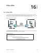
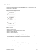
6 IPSec VPN Chapter Chapter 16 C H AP T ER 1 6 16.1 IPSec VPN A virtual private network (VPN) provides secure communications over the the Internet. Internet Protocol Security (IPSec) is a standards-based VPN that provides confidentiality, data integrity, and authentication. This chapter shows you how to configure the Router’s VPN settings. Figure 75 IPSec Fields Summary Remote Network Local Network VPN Tunnel Click Advanced Setup > IPSec VPN to view and manage your VPN tunnel policies.
This screen contains the following fields: Table 69 IPSec VPN LABEL DESCRIPTION Connection Name The name of the VPN policy. Remote Gateway This is the IP address of the remote IPSec router in the IKE SA. Local Addresses This displays the IP address(es) on the LAN behind your Router. Remote Addresses This displays the IP address(es) on the LAN behind the remote IPSec’s router. Remove Select entries and click the Remove button to delete them.
16.2 IPSec VPN Add Screen Use these settings to add IPSec VPN policies. Click the Add New Connection button in the Advanced Setup > IPSec VPN screen to open this screen as shown next.
This screen contains the following fields: Table 70 IPSec VPN: Add LABEL DESCRIPTION IPSec Connection Name Enter the name of the VPN policy. IP Version Set whether this policy uses IPv4 or IPv6. Tunnel Mode Select the security protocol to use in the IPSec SA. AH (RFC 2402) - provides integrity, authentication, sequence integrity (replay resistance), and non-repudiation but not encryption. ESP (RFC 2406) - provides encryption and the same services offered by AH, but its authentication is weaker.
Table 70 IPSec VPN: Add (continued) LABEL DESCRIPTION Key Exchange Method Select the key exchange method: Auto(IKE) - Select this to use automatic IKE key management VPN connection policy. Manual - Select this option to configure a VPN connection policy that uses a manual key instead of IKE key management. This may be useful if you have problems with IKE key management. Note: Only use manual key as a temporary solution, because it is not as secure as a regular IPSec SA.
Table 70 IPSec VPN: Add (continued) LABEL DESCRIPTION Encryption Algorithm Select which key size and encryption algorithm to use in the IKE SA.
Table 70 IPSec VPN: Add (continued) LABEL DESCRIPTION Select Diffie-Hellman Group for Key Exchange Select which Diffie-Hellman key group you want to use for encryption keys. Choices for number of bits in the random number are: 768, 1024, 1536, 2048, 3072, 4096, 6114, and 8192. The longer the key, the more secure the encryption, but also the longer it takes to encrypt and decrypt information. Both routers must use the same DH key group.
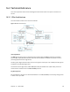
16.3 Technical Reference This section provides some technical background information about the topics covered in this section. 16.3.1 IPSec Architecture The overall IPSec architecture is shown as follows. Figure 78 IPSec Architecture IPSec Algorithms The ESP (Encapsulating Security Payload) Protocol (RFC 2406) and AH (Authentication Header) protocol (RFC 2402) describe the packet formats and the default standards for packet structure (including implementation algorithms).
16.3.2 Encapsulation The two modes of operation for IPSec VPNs are Transport mode and Tunnel mode. At the time of writing, the Router supports Tunnel mode only. Figure 79 Transport and Tunnel Mode IPSec Encapsulation Transport Mode Transport mode is used to protect upper layer protocols and only affects the data in the IP packet.
16.3.3 IKE Phases There are two phases to every IKE (Internet Key Exchange) negotiation – phase 1 (Authentication) and phase 2 (Key Exchange). A phase 1 exchange establishes an IKE SA and the second one uses that SA to negotiate SAs for IPSec. Figure 80 Two Phases to Set Up the IPSec SA In phase 1 you must: • Choose a negotiation mode. • Authenticate the connection by entering a pre-shared key. • Choose an encryption algorithm. • Choose an authentication algorithm.
16.3.4 Negotiation Mode The phase 1 Negotiation Mode you select determines how the Security Association (SA) will be established for each connection through IKE negotiations. • Main Mode ensures the highest level of security when the communicating parties are negotiating authentication (phase 1). It uses 6 messages in three round trips: SA negotiation, Diffie-Hellman exchange and an exchange of nonces (a nonce is a random number).
Transport mode ESP with authentication is not compatible with NAT. Table 71 VPN and NAT SECURITY PROTOCOL MODE NAT AH Transport N AH Tunnel N ESP Transport N ESP Tunnel Y 16.3.6 VPN, NAT, and NAT Traversal NAT is incompatible with the AH protocol in both transport and tunnel mode.
Finally, NAT is compatible with ESP in tunnel mode because integrity checks are performed over the combination of the "original header plus original payload," which is unchanged by a NAT device. The compatibility of AH and ESP with NAT in tunnel and transport modes is summarized in the following table. Table 72 VPN and NAT SECURITY PROTOCOL MODE NAT AH Transport N AH Tunnel N ESP Transport Y* ESP Tunnel Y Y* - This is supported in the Router if you enable NAT traversal. 16.3.
Table 73 Local ID Type and Content Fields (continued) LOCAL ID TYPE= CONTENT= E-mail Type an e-mail address (up to 31 characters) by which to identify this Router. The domain name or e-mail address that you use in the Local ID Content field is used for identification purposes only and does not need to be a real domain name or email address. 16.3.7.1 ID Type and Content Examples Two IPSec routers must have matching ID type and content configuration in order to set up a VPN tunnel.
16.3.9 Diffie-Hellman (DH) Key Groups Diffie-Hellman (DH) is a public-key cryptography protocol that allows two parties to establish a shared secret over an unsecured communications channel. Diffie-Hellman is used within IKE SA setup to establish session keys. Upon completion of the Diffie-Hellman exchange, the two peers have a shared secret, but the IKE SA is not authenticated. For authentication, use pre-shared keys.
Certificates 17 Chapter Chapter 17 C H AP T ER 1 7 17.1 Local Certificates The Router can use certificates (also called digital IDs) to authenticate users. Certificates are based on public-private key pairs. A certificate contains the certificate owner’s identity and public key. Certificates provide a way to exchange public keys for use in authentication. Click Advanced Setup > Certificates > Local to manage the Router’s list of certificates and certification requests.
Table 76 Local Certificates (continued) LABEL DESCRIPTION Action Click the View button to open a screen with an in-depth list of information about the certificate (or certification request). For a certification request, click Load Signed to import the signed certificate. Click the Remove button to delete the certificate (or certification request). You cannot delete a certificate that one or more features is configured to use.
Table 77 Create Certificate Request LABEL DESCRIPTION Certificate Name Type up to 63 ASCII characters (not including spaces) to identify this certificate. Common Name Select Auto to have the Router configure this field automatically. Or select Customize to enter it manually. Type the IP address (in dotted decimal notation), domain name or e-mail address in the field provided. The domain name or e-mail address can be up to 63 ASCII characters.
17.1.2 Load Signed Certificate After you create a certificate request and have it signed by a Certificate Authority, in the Local Certificates screen click the certificate request’s Load Signed button to import the signed certificate into the Router. You must remove any spaces from the certificate’s filename before you can import it. Figure 85 Load Signed Certificate Table 78 Load Signed Certificate 17.2 LABEL DESCRIPTION Certificate Name This is the name of the signed certificate.
Click Advanced Setup > Certificates > Trusted CA to open the Trusted CA screen. Figure 86 Trusted CA Table 79 Trusted CA LABEL DESCRIPTION Name This field displays the name used to identify this certificate. Subject This field displays information that identifies the owner of the certificate, such as Common Name (CN), OU (Organizational Unit or department), Organization (O), State (ST) and Country (C). It is recommended that each certificate have unique subject information.
17.2.1 View Trusted CA Certificate Click the View icon in the Trusted CA screen to open the following screen. Use this screen to view in-depth information about the certification authority’s certificate. Figure 87 Trusted CA: View The following table describes the fields in this screen. Table 80 Trusted CA: View LABEL DESCRIPTION Name This field displays the identifying name of this certificate. Type This field displays general information about the certificate.
17.2.2 Import Trusted CA Certificate Click the Trusted CA screen’s Import Certificate button to open the following screen. The Router trusts any valid certificate signed by any of the imported trusted CA certificates. Figure 88 Trusted CA: Import Certificate The following table describes the fields in this screen. Table 81 Trusted CA: Import Certificate LABEL DESCRIPTION Certificate Name Type a name for the signed certificate.
18.1 Power Management 18 Chapter Chapter 18 C H AP T ER 1 8 Power Management Click Advanced Setup > Power Management to control hardware modules to reduce power consumption. Use the control buttons to select the desired option, click Apply and check the status response.
Table 82 Power Management LABEL DESCRIPTION MIPS CPU Clock divider when Idle Select Enable to reduce the MIPS CPU’s clock when idle to reduce power usage. Clear this to always run the MIPS CPU at full speed. Wait instruction when Idle Select Enable to put the CPU to sleep when idle to reduce power usage. Clear this to always keep the CPU running. Energy Efficient Ethernet Select Enable to set the Ethernet interfaces to power saving mode. Clear this to turn off power saving on the Ethernet interfaces.
19.1 Multicast 19 Chapter Chapter 19 C H AP T ER 1 9 Multicast Click Advanced Setup > Multicast to configure multicast and IGMP and MLD group settings.
s: My Network Places: Properties: Example Table 83 Multicast LABEL DESCRIPTION Multicast Precedence Set the Router’s multicast precedence (1 to 9) or disable multicast on the Router. The lower the number, the higher the Router’s multicast priority. IGMP/MLD Configuration Default Version Enter the version of IGMP (1~3) and MLD (1~2) that you want the Router to use on the WAN.
Wireless 20 Chapter Chapter 20 C H AP T ER 2 0 20.1 Wireless Basic Use the Advanced Setup > Wireless screens to configure the 2.4 GHz wireless network. Click Advanced Setup > Wireless to enable or disable the 2.4 GHz Wireless LAN and configure basic settings. If you are configuring the Router from a computer connected to the wireless LAN and you change the Router’s SSID or security settings, you will lose your wireless connection when you press Apply to confirm.
Figure 91 Wireless Basic Table 84 Wireless Basic LABEL DESCRIPTION Enable Wireless Select this check box to activate the wireless LAN. Enable Wireless Hotspot2.0 Hide Access Point Select this check box to hide the SSID in the outgoing beacon frame so a station cannot obtain the SSID through scanning using a site survey tool. Clients Isolation Select this to keep the wireless clients in this SSID from communicating with each other directly through the Router.
Table 84 Wireless Basic (continued) LABEL DESCRIPTION Enable Wireless Multicast Forwarding Select this check box to have the Router convert wireless multicast traffic (IGMP version 2 or 3) into wireless unicast traffic to reduce the traffic load. This function can improve the transmission quality of video services (for example, IPTV). SSID Enter a descriptive name for the wireless LAN. BSSID This shows the MAC address of the wireless interface on the Device when wireless LAN is enabled.
20.2 Wireless Security Click Wireless > Security to open the Security screen. Set Network Authentication to Open and WEP Encryption to Disabled to allow wireless stations to communicate with the Router without any data encryption or authentication. If you do not enable any wireless security on your Router, your network is accessible to any wireless networking device that is within range.
Figure 92 Wireless Security Chapter 20 Wireless 144
Table 85 Wireless Security LABEL DESCRIPTION Enable WPS Use WiFi Protected Setup (WPS) to quickly set up a wireless network without having to manually configure settings. Set up each WPS connection between two devices at a time. Add Client Use this section to add a wireless client to the wireless network. Select Use STA PIN to add a client by entering the client’s Personal Identification Number (PIN) in the field that displays when you select this option.
Table 85 Wireless Security LABEL DESCRIPTION WPA/WAPI passphrase This field displays when you select WPA2-PSK or Mixed WPA2/WPA -PSK. WPA Group Rekey Interval Set the rate at which the AP (if using WPA2/WPA-PSK key management) or RADIUS server (if using WPA(2) key management) sends a new group key out to all clients. The re-keying process is the WPA(2) equivalent of automatically changing the WEP key for an AP and all stations in a WLAN on a periodic basis.
20.3 Wireless MAC Filter Click Wireless > MAC Filter to open the MAC Filter screen. This screen allows you to configure the Router to give exclusive access to specific devices (Allow) or exclude specific devices from accessing the Router (Deny). Every Ethernet device has a unique MAC (Media Access Control) address assigned at the factory. It consists of six pairs of hexadecimal characters, for example, 00:A0:C5:00:00:02. You need to know the MAC addresses of the devices to configure this screen.
20.3.1 Wireless MAC Filter Add Use this screen to add MAC address entries. Click Wireless > MAC Filter > Add to open the following screen. Figure 94 Wireless MAC Filter Add Table 87 Wireless MAC Filter Add LABEL DESCRIPTION MAC Address Enter the MAC address of the wireless device that is to be allowed or denied access to the Router. Enter the MAC addresses in a valid MAC address format, that is, six hexadecimal character pairs, for example, 12:34:56:78:9a:bc.
20.4 Wireless Advanced Click Wireless > Advanced to configure advanced wireless settings.
Table 88 Wireless Advanced LABEL DESCRIPTION Band Select an operating band to use. Channel Select an operating channel to use. The choices depend on your particular region. Either select a channel or use Auto to have the Router automatically determine a channel to use. If you are having problems with wireless interference, changing the channel may help. Try to use a channel that is as many channels away from any channels used by neighboring APs as possible.
Table 88 Wireless Advanced (continued) LABEL DESCRIPTION OBSS CoExistance Select Enable to allow coexistence between 20 MHZ and 40 MHZ Overlapping Basic Service Sets (OBSS) in wireless local area networks. RX Chain Power Save Select Enable to activate the RX Chain Power Save feature. It turns off one of the Receive chains to save power. RX Chain Power Save Quiet Time Specify the number of seconds the traffic must be below the PPS value before the Rx Chain Power Save feature is activated.
Table 88 Wireless Advanced (continued) LABEL DESCRIPTION Transmit Power Set the output power of the Router. If there is a high density of APs in an area, decrease the output power to reduce interference with other APs. WMM (Wi-Fi Multimedia) Use WMM (Wifi MultiMedia) to prioritize services in wireless traffic. Select Auto to automatically prioritize services according to the ToS value in the IP header of packets.
The following table describes the labels in this menu. Table 89 Wireless Station Info LABEL DESCRIPTION MAC This displays the MAC address (in XX:XX:XX:XX:XX:XX format) of a connected wireless station. Associated This is the time that the wireless client associated with the Router. Authorized This is the time that the wireless client’s connection to the Router was authorized. SSID This is the name of the wireless network on the Router to which the wireless client is connected.
If you are configuring the Router from a computer connected to the wireless LAN and you change the Router’s SSID or security settings, you will lose your wireless connection when you press Apply to confirm. You must then change the wireless settings of your computer to match the Router’s new settings. Figure 97 Wireless 5GHz Basic Table 90 Wireless 5GHz Basic LABEL DESCRIPTION Enable Wireless Guest Network Select this check box to activate the guest wireless LAN.
Table 90 Wireless 5GHz Basic (continued) LABEL DESCRIPTION SSID Enter a descriptive name for the wireless LAN. BSSID This shows the MAC address of the wireless interface on the Device when wireless LAN is enabled. Country Select the country you have the Router in. This has the Router use the correct frequency bands. Channel Select an operating channel to use. The choices depend on your particular region.
20.7 Wireless 5GHz Advanced Screen Click Wireless 5GHz > Advanced to configure advanced 5 GHz wireless settings. Figure 98 Wireless 5GHz Advanced Table 91 Wireless 5GHz Advanced LABEL DESCRIPTION Region Select an operating band to use. Bandwidth Select whether the Device uses a wireless channel width of 20MHz, 40MHz, or 80MHz.
Table 91 Wireless 5GHz Advanced (continued) LABEL DESCRIPTION DTIM Delivery Traffic Indication Message (DTIM) is the time period after which broadcast and multicast packets are transmitted to mobile clients in the Power Saving mode. A high DTIM value can cause clients to lose connectivity with the network. This value can be set from 1 to 100. Beamforming Select this option to have the Router focus the wireless signal and aim it directly at the wireless clients. Clear this option to disable beamforming.
Figure 99 Wireless 5GHz WPS Table 92 Wireless 5GHz WPS LABEL DESCRIPTION Enable WPS Use WiFi Protected Setup (WPS) to quickly set up a wireless network without having to manually configure settings. Set up each WPS connection between two devices at a time. Add Client Use this section to add a wireless client to the wireless network. Select Use STA PIN to add a client by entering the client’s Personal Identification Number (PIN) in the field that displays when you select this option.
Table 92 Wireless 5GHz WPS (continued) LABEL DESCRIPTION Select SSID Select an SSID for which to configure security settings. Enabled WPS Use WiFi Protected Setup (WPS) to quickly set up a wireless network without having to manually configure settings. Set up each WPS connection between two devices at a time. WPS is not available when using WPA or WPA 2. Setup WPS AP Mode Use an external registrar (like Windows Vista) configure the Router’s wireless security settings.
20.9 Wireless 5GHz MAC Filter Click Wireless 5GHz > MAC Filter to open the MAC Filter screen. This screen allows you to configure the Router to give exclusive access to specific devices (Allow) or exclude specific devices from accessing the Router (Deny). Every Ethernet device has a unique MAC (Media Access Control) address assigned at the factory. It consists of six pairs of hexadecimal characters, for example, 00:A0:C5:00:00:02. You need to know the MAC addresses of the devices to configure this screen.
20.9.1 Wireless MAC Filter Add Use this screen to add MAC address entries. Click Wireless > MAC Filter > Add to open the following screen. Figure 101 Wireless MAC Filter Add Table 94 Wireless MAC Filter Add LABEL DESCRIPTION MAC Address Enter the MAC address of the wireless device that is to be allowed or denied access to the Router. Enter the MAC addresses in a valid MAC address format, that is, six hexadecimal character pairs, for example, 12:34:56:78:9a:bc.
20.10 Wireless 5GHz Bridge The Router can function as a wireless network bridge to wirelessly connect two or more APs. Figure 102 Connecting Wireless Networks Using WDS Use this screen to set up your Wireless Distribution System (WDS) links between the Router and other wireless APs. You need to know the MAC address of the peer device. Once the security settings of peer sides match one another, the connection between devices is made.
Click Wireless 5GHz > Wireless Bridge to display the following screen. Figure 104 Wireless 5GHz Bridge Table 95 Wireless Bridge LABEL DESCRIPTION Remote Bridges MAC Address Type the MAC address of the peer device in a valid MAC address format (six hexadecimal character pairs, for example 12:34:56:78:9a:bc). Apply/Save Click this to save and apply your changes. 20.
The following table describes the labels in this menu. Table 96 Wireless 5GHz Station Info LABEL DESCRIPTION Select SSID Select an SSID for which to display the authenticated wireless stations and their status. MAC This displays the MAC address (in XX:XX:XX:XX:XX:XX format) of a connected wireless station. RSSI This displays the Received Signal Strength Indication of the wireless station’s connection to the 5 GHz network. Refresh Click this button to update the information in the screen.
21.1 Voice 21 Chapter Chapter 21 C H AP T ER 2 1 SIP Account The Router uses a SIP account to make outgoing VoIP calls and check if an incoming call’s destination number matches your SIP account’s SIP number. In order to make or receive a VoIP call, you need to enable and configure a SIP account, and map it to a phone port. The SIP account contains information that allows your Router to connect to your VoIP service provider. Use this screen to maintain information about each SIP account.
Chapter 21 Voice 166
Each field is described in the following table. Table 97 SIP Account LABEL DESCRIPTION Service Provider Selection Select the SIP service provider profile you want to use for the SIP account you configure in this screen. If you change this field, the screen automatically refreshes. SIP Account Selection Select the SIP account you want to see in this screen. If you change this field, the screen automatically refreshes. Select ADD_NEW to create a new SIP account on the Router.
Table 97 SIP Account (continued) LABEL DESCRIPTION Primary Compression Type Select the type of voice coder/decoder (codec) that you want the Router to use. G.711 provides high voice quality but requires more bandwidth (64 kbps). G.711 is the default codec used by phone companies and digital handsets. Secondary Compression Type • • • Third Compression Type G.711a is typically used in Europe. G.711u is typically used in North America and Japan. G.711a_VBD is used in fax transmission.
Table 97 SIP Account (continued) LABEL DESCRIPTION Enable Unconditional Forward Select this if you want the Router to forward all incoming calls to the specified phone number. Enable Busy Forward Select this if you want the Router to forward incoming calls to the specified phone number if the phone port is busy. Specify the phone number in the To Number field on the right. Specify the phone number in the To Number field on the right.
21.2 SIP Server Click Voice > SIP Server to open the SIP Server screen. Use this screen to configure the SIP server information, QoS for VoIP calls, the numbers for certain phone functions, and dialing plan.
Each field is described in the following table. Table 98 SIP Server LABEL DESCRIPTION Service Provider Selection Select the SIP service provider profile you want to see in this screen. If you change this field, the screen automatically refreshes. Select ADD_NEW to create a new SIP service provider profile on the Router. Delete Click this button to remove the SIP service provider profile selected in the Service Provider Selection field.
Table 98 SIP Server (continued) LABEL DESCRIPTION REGISTER Server Address Enter the IP address or domain name of the SIP register server, if your VoIP service provider gave you one. Otherwise, enter the same address you entered in the SIP Server Address field. You can use up to 95 printable ASCII characters. REGISTER Server Port Enter the SIP register server’s listening port number, if your VoIP service provider gave you one.
Table 98 SIP Server (continued) LABEL DESCRIPTION Don't send reInvite to the remote party when there are multiple codecs answered in the SDP Do not send a re-Invite packet to the remote party when the remote party answers that it can support multiple codecs?? Bound Interface Name Bound Interface Name If you select LAN or Any_WAN, the Router automatically activates the VoIP service when any LAN or WAN connection is up. If you select Multi_WAN, you also need to select the pre-configured WAN connections.
Table 98 SIP Server (continued) LABEL DESCRIPTION FAX Option This field controls how the Router handles fax messages. Select G.711 Fax Passthrough to have the use G.711 to send fax messages. The peer devices must also use G.711. Select T.38 Fax Relay to have the Router send fax messages as UDP or TCP/IP packets through IP networks. This provides better quality, but it may have interoperability problems. The peer devices must also use T.38.
Table 98 SIP Server (continued) LABEL DESCRIPTION Internal Call Specify the key combinations that you can enter to call the phone(s) connected to the Router. Call Transfer Specify the key combinations that you can enter to transfer a call to another phone. Unconditional Call Forward Enable Specify the key combinations that you can enter to forward all incoming calls to the phone number you specified in the SIP > SIP Account screen.
Table 98 SIP Server (continued) LABEL DESCRIPTION Dialing Interval Selection Dialing Interval Selection Enter the number of seconds the Router should wait after you stop dialing numbers before it makes the phone call. The value depends on how quickly you dial phone numbers. If you select Immediate Dial Enable, you can press the pound key (#) to tell the Router to make the phone call immediately, regardless of this setting.
• indicates the number after the colon replaces the number before the colon in an angle bracket <>. For example, (<:1212> xxxxxxx) means the Router automatically prefixes the translated-number “1212” to the number you dialed before making the call. This can be used for local calls in the US. (<9:> xxx xxxxxxx) means the Router automatically removes the specified prefix “9” from the number you dialed before making the call.
Table 99 Phone Region 21.4 LABEL DESCRIPTION Apply Click this to save your changes and to apply them to the Router. Cancel Click this to set every field in this screen to its last-saved value. Call Rule Click Voice > Call Rule to manage speed-dial numbers for outgoing calls. Speed dial provides shortcuts for dialing frequently-used (VoIP) phone numbers. You also have to create speed-dial entries if you want to call SIP numbers that contain letters.
Table 100 Call Rule LABEL DESCRIPTION Description Enter a name to identify the party you call when you dial the speed-dial number. You can use up to 127 printable ASCII characters. Add Click this to use the information in the Speed Dial section to update the Phone Book section. Phone Book Use this section to look at all the speed-dial entries and to erase them. # This field displays the speed-dial number you should dial to use this entry.
Table 101 Call History Summary 21.6 LABEL DESCRIPTION No. This is a read-only index number. Date This is the date when the calls were made. Total Calls This displays the total number of calls from or to your SIP numbers that day. Outgoing Calls This displays how many calls originated from you that day. Incoming Calls This displays how many calls you received that day. Missing Calls This displays how many incoming calls were not answered that day.
21.7 Incoming Calls Use this screen to see detailed information for each incoming call from someone calling you. Click Voice > Incoming. The following screen displays. Figure 112 Incoming Calls Each field is described in the following table. Table 103 Incoming Calls LABEL DESCRIPTION Refresh Click this button to renew the received call list. Clear All Click this button to remove all entries from the received call list. No. This is a read-only index number.
SIP The Session Initiation Protocol (SIP) is an application-layer control (signaling) protocol that handles the setting up, altering and tearing down of voice and multimedia sessions over the Internet. SIP signaling is separate from the media for which it handles sessions. The media that is exchanged during the session can use a different path from that of the signaling. SIP handles telephone calls and can interface with traditional circuit-switched telephone networks.
Authorization Requirements SIP registrations (and subsequent SIP requests) require a username and password for authorization. These credentials are validated via a challenge / response system using the HTTP digest mechanism (as detailed in RFC 3261, "SIP: Session Initiation Protocol"). SIP Servers SIP is a client-server protocol. A SIP client is an application program or device that sends SIP requests. A SIP server responds to the SIP requests.
2 The SIP proxy server forwards the call invitation to C. Figure 114 SIP Proxy Server SIP Redirect Server A SIP redirect server accepts SIP requests, translates the destination address to an IP address and sends the translated IP address back to the device that sent the request. Then the client device that originally sent the request can send requests to the IP address that it received back from the redirect server. Redirect servers do not initiate SIP requests.
3 Client device A then sends the call invitation to client device C. Figure 115 SIP Redirect Server SIP Register Server A SIP register server maintains a database of SIP identity-to-IP address (or domain name) mapping. The register server checks your user name and password when you register. RTP When you make a VoIP call using SIP, the RTP (Real time Transport Protocol) is used to handle voice data transfer. See RFC 1889 for details on RTP.
Table 104 SIP Call Progression (continued) A B 3. OK 4. ACK 5.Dialogue (voice traffic) 6. BYE 7. OK 1 A sends a SIP INVITE request to B. This message is an invitation for B to participate in a SIP telephone call. 2 B sends a response indicating that the telephone is ringing. 3 B sends an OK response after the call is answered. 4 A then sends an ACK message to acknowledge that B has answered the call. 5 Now A and B exchange voice media (talk).
The following figure shows the SIP and session traffic flow between the user agents (UA 1 and UA 2) and the proxy servers (this example shows two proxy servers, PROXY 1 and PROXY 2). Figure 116 SIP Call Through Proxy Servers PROXY 1 PROXY 2 SIP SIP SIP SIP & RTP UA 1 UA 2 The following table shows the SIP call progression.
Table 105 SIP Call Progression UA 1 PROXY 1 PROXY 2 UA 2 BYE 200 OK 1 User Agent 1 sends a SIP INVITE request to Proxy 1. This message is an invitation to User Agent 2 to participate in a SIP telephone call. Proxy 1 sends a response indicating that it is trying to complete the request. 2 Proxy 1 sends a SIP INVITE request to Proxy 2. Proxy 2 sends a response indicating that it is trying to complete the request. 3 Proxy 2 sends a SIP INVITE request to User Agent 2.
Voice Activity Detection/Silence Suppression Voice Activity Detection (VAD) detects whether or not speech is present. This lets the Router reduce the bandwidth that a call uses by not transmitting “silent packets” when you are not speaking. Comfort Noise Generation When using VAD, the Router generates comfort noise when the other party is not speaking. The comfort noise lets you know that the line is still connected as total silence could easily be mistaken for a lost connection. Echo Cancellation G.
4 You can continue to add, listen to, or delete tones, or you can hang up the receiver when you are done. Listening to Custom Tones Do the following to listen to a custom tone: 1 Pick up the phone and press “****” on your phone’s keypad and wait for the message that says you are in the configuration menu. 2 Press a number from 1201~1208 followed by the “#” key to listen to the tone. 3 You can continue to add, listen to, or delete tones, or you can hang up the receiver when you are done.
DSCP and Per-Hop Behavior DiffServ defines a new DS (Differentiated Services) field to replace the Type of Service (TOS) field in the IP header. The DS field contains a 2-bit unused field and a 6-bit DSCP field which can define up to 64 service levels. The following figure illustrates the DS field. DSCP is backward compatible with the three precedence bits in the ToS octet so that non-DiffServ compliant, ToS-enabled network device will not conflict with the DSCP mapping.
21.8.2.1 The Flash Key Flashing means to press the hook for a short period of time (a few hundred milliseconds) before releasing it. On newer telephones, there should be a "flash" key (button) that generates the signal electronically. If the flash key is not available, you can tap (press and immediately release) the hook by hand to achieve the same effect. However, using the flash key is preferred since the timing is much more precise.
Press the flash key and then “1” to disconnect the current call and resume the call on hold. If you hang up the phone but a caller is still on hold, there will be a remind ring. European Call Waiting This allows you to place a call on hold while you answer another incoming call on the same telephone (directory) number. If there is a second call to a telephone number, you will hear a call waiting tone. Take one of the following actions. • Reject the second call. Press the flash key and then press “0”.
21.8.2.3 USA Type Supplementary Services This section describes how to use supplementary phone services with the USA Type Call Service Mode. Commands for supplementary services are listed in the table below. After pressing the flash key, if you do not issue the sub-command before the default sub-command timeout (2 seconds) expires or issue an invalid sub-command, the current operation will be aborted.
USA Three-Way Conference Use the following steps to make three-way conference calls. 1 When you are on the phone talking to someone (party A), press the flash key to put the caller on hold and get a dial tone. 2 Dial a phone number directly to make another call (to party B). 3 When party B answers the second call, press the flash key to create a three-way conversation. 4 Hang up the phone to drop the connection.
Chapter 21 Voice 196
22.1 Diagnostics 22 Chapter Chapter 22 C H AP T ER 2 2 Diagnostics Click Diagnostics to test the Router’s connections. Figure 118 Diagnostics Click Rerun Diagnostic Tests to perform the tests again.
22.2 Ping/TraceRoute/Nslookup Ping, traceroute, and nslookup help check availability of remote hosts and also help troubleshoot network or Internet connections. Click Diagnostics > Ping&TraceRoute&Nslookup to open the screen shown next. Figure 119 Ping/TraceRoute/Nslookup Table 110 Ping/TraceRoute/Nslookup LABEL DESCRIPTION Ping Type an IPv4 or IPv6 address to which to test a connection. Click Ping and the ping statistics will show in the diagnostic.
Settings 23 Chapter Chapter 23 C H AP T ER 2 3 This chapter describes how to manage your Router’s configuration. 23.1 Backup Configuration Using the Web Configurator Click Management > Settings > Backup to open the following screen. Use this screen to back up (save) the Router’s current configuration to a file on your computer. Once your Router is configured and functioning properly, it is highly recommended that you back up your configuration file before making configuration changes.
23.2 Restore Configuration Using the Web Configurator Click Management > Settings > Update to open the following screen. Use this screen to upload a new or previously saved configuration file from your computer to your Router. Figure 121 Settings: Update Table 111 Settings: Update LABEL DESCRIPTION Settings File Name Type in the location of the file you want to upload in this field or click Browse... to find it. Browse... Click Browse... to find the file you want to upload.
23.3 Restoring Factory Defaults Click Management > Settings > Restore Default to open the following screen. Figure 123 Management > Settings > Restore Default Click Restore Default Settings to clear all user-entered configuration information and return the Router to its factory defaults. You can also press the RESET button on the rear panel to reset the factory defaults of your Router.
24.1 24 Logs Chapter Chapter 24 C H AP T ER 2 4 Logs The Web Configurator allows you to choose which categories of events and/or alerts to have the Router log and then display the logs or have the Router send them to an administrator (as e-mail) or to a syslog server. 24.1.1 What You Need To Know The following terms and concepts may help as you read this chapter. Alerts and Logs An alert is a type of log that warrants more serious attention.
Table 112 Syslog Severity Levels (continued) 24.2 CODE SEVERITY 6 Informational: The syslog contains an informational message. 7 Debug: The message is intended for debug-level purposes. System Log Use the System Log screen to see the system logs. Click Management > System Log > View System Log to open the System Log screen. Figure 124 System Log The following table describes the fields in this screen. Table 113 System Log LABEL DESCRIPTION Date/Time This field displays when the log was recorded.
Table 113 System Log (continued) 24.3 LABEL DESCRIPTION Messages This field states the reason for the log. Refresh Click this to renew the log screen. Close Click this to close the log screen. System Log Configuration To change your Router’s log settings, click Management > System Log > Configure System Log. The screen appears as shown. Figure 125 System Log Configuration The following table describes the fields in this screen.
Table 114 System Log Configuration (continued) 24.4 LABEL DESCRIPTION Server IP Address Enter the IP address of the syslog server that will log the selected categories of logs. Server UDP Port Enter the port number used by the syslog server. Apply/Save Click this button to save your changes. Security Log Use the Security Log screen to see the system logs. Click Management > Security Log > View to open the Security Log screen.
The following table describes the fields in this screen. Table 115 Security Log LABEL DESCRIPTION Date/Time This field displays when the log was recorded. Facility The log facility allows you to send logs to different files in the syslog server. Refer to the documentation of your syslog program for more details. Severity This field displays the severity level of the logs that the device is to send to this syslog server. Messages This field states the reason for the log.
25.1 SNMP 25 Chapter Chapter 25 C H AP T ER 2 5 SNMP Agent Simple Network Management Protocol is a protocol used for exchanging management information between network devices. Your Router supports SNMP agent functionality, which allows a manager station to manage and monitor the Router through the network. The Router supports SNMP version one (SNMPv1) and version two (SNMPv2c). The next figure illustrates an SNMP management operation.
SNMP itself is a simple request/response protocol based on the manager/agent model. The manager issues a request and the agent returns responses using the following protocol operations: • Get - Allows the manager to retrieve an object variable from the agent. • GetNext - Allows the manager to retrieve the next object variable from a table or list within an agent.
Table 116 Management > SNMP Agent (continued) LABEL DESCRIPTION System Contact Enter the SNMP system contact. Trap Manager IP Type the IP address of the station to send your SNMP traps to. Save/Apply Click this to save your changes back to the Router.
26.1 TR-069 Client 26 Chapter Chapter 26 C H AP T ER 2 6 TR-069 Client Click Management > TR-069 Client to open the following screen. Use this screen to configure your Router to be managed by an ACS (Auto Configuration Server). Figure 129 TR-069 Client Table 117 TR-069 Client LABEL DESCRIPTION Inform Select Enable for the Router to send periodic inform via TR-069 on the WAN. Otherwise, select Disable.
Table 117 TR-069 Client (continued) LABEL DESCRIPTION ACS User Name Enter the TR-069 user name for authentication with the auto-configuration server. ACS Password Enter the TR-069 password for authentication with the auto-configuration server. WAN Interface used by TR-069 client Select a WAN interface through which the TR-069 traffic passes. If you select Any_WAN, you should also select the pre-configured WAN connection(s).
27.1 Internet Time 27 Chapter Chapter 27 C H AP T ER 2 7 Internet Time Click Management > Internet Time to configure the Router to get the time from time servers on the Internet.
The following table describes the fields in this screen. Table 118 Internet Time LABEL DESCRIPTION Automatically synchronize with Internet time servers Select this to have the Router get the time from the specified Internet time servers. First ~ Fifth NTP time server Select an NTP time server from the drop-down list box. Otherwise, select Other and enter the IP address or URL (up to 29 extended ASCII characters in length) of your time server. Select None if you don’t want to configure the time server.
28.1 User Passwords 28 Chapter Chapter 28 C H AP T ER 2 8 User Passwords Click Management > Access Control > Passwords to change the login password. Figure 131 Use Passwords Table 119 User Passwords LABEL DESCRIPTION User Name Enter the name of one of the Router system accounts. Old Password Type the account’s default password or existing password. New Password Type your new system password (up to 30 characters).
29.1 GPON Password 29 Chapter Chapter 29 C H AP T ER 2 9 GPON Password Click Management > GPON Password to enter the password for your GPON Internet access account. Figure 132 GPON Password Table 120 GPON Password LABEL DESCRIPTION Enter GPON Password Enter the password for your GPON Internet access account. Apply Click this button to save and apply your changes.
Update Software 30 Chapter Chapter 30 C H AP T ER 3 0 30.1 Update Software Click Management > Update Software to open the following screen where you can upload new software to your Router. You can download new software releases from your ISP to use to upgrade your device’s performance. Only use software for your device’s specific model. Refer to the label on the bottom of your Router. The upload process uses HTTP (Hypertext Transfer Protocol) and may take up to two minutes.
After you see the software updating screen, wait two minutes before logging into the Router again. The Router automatically restarts in this time causing a temporary network disconnect. In some operating systems, you may see the following icon on your desktop. Figure 134 Network Temporarily Disconnected After two minutes, log in again and check your new software version in the Device Info screen.
Reboot 31 Chapter Chapter 31 C H AP T ER 3 1 31.1 Restart Using the Web Configurator Click Management > Reboot to open the following screen. Use this screen to restart the .
Troubleshooting 32 Chapter Chapter 32 C H AP T ER 3 2 32.1 Overview This chapter offers some suggestions to solve problems you might encounter. The potential problems are divided into the following categories. • Power, Hardware Connections, and LEDs • Router Access and Login • Internet Access • Wireless Internet Access • Phone Calls and VoIP • UPnP 32.2 Power, Hardware Connections, and LEDs The Router does not turn on. None of the LEDs turn on. 1 Make sure the Router is turned on.
4 Turn the Router off and on. 5 If the problem continues, contact the vendor. 32.3 Router Access and Login I forgot the IP address for the Router. 1 The default IP address is 192.168.1.1. 2 If you changed the IP address and have forgotten it, you might get the IP address of the Router by looking up the IP address of the default gateway for your computer. To do this in most Windows computers, click Start > Run, enter cmd, and then enter ipconfig.
Advanced Suggestions • Try to access the Router using another service, such as Telnet. If you can access the Router, check the remote management settings and firewall rules to find out why the Router does not respond to HTTP. • If your computer is connected wirelessly, use a computer that is connected to a ETHERNET port. I can see the Login screen, but I cannot log in to the Router. 1 Make sure you have entered the user name and password correctly.
4 If you are trying to access the Internet wirelessly, make sure you have enabled the wireless LAN by the Wifi/WPS button or the Network Setting > Wireless > General screen. 5 Disconnect all the cables from your device, and follow the directions in Section 1.2 on page 9. again. 6 If the problem continues, contact your ISP. I cannot access the Internet anymore. I had access to the Internet (with the Router), but my Internet connection is not available anymore.
To optimize the speed and quality of your wireless connection, you can: • Move your wireless device closer to the AP if the signal strength is low. • Reduce wireless interference that may be caused by other wireless networks or surrounding wireless electronics such as cordless phones. • Place the AP where there are minimum obstacles (such as walls and ceilings) between the AP and the wireless client.
2 You can also check the VoIP status in the System Info screen. 3 If the VoIP settings are correct, use speed dial to make peer-to-peer calls. If you can make a call using speed dial, there may be something wrong with the SIP server, contact your VoIP service provider. 32.7 UPnP When using UPnP and the Router reboots, my computer cannot detect UPnP and refresh My Network Places > Local Network. 1 Disconnect the Ethernet cable from the Router’s LAN port or from your computer.
A Appendix A Safety Warnings • • • • • • • • • • • • • • • • • • • • • Appendix A P P EN D IX A Do NOT use this product near water, for example, in a wet basement or near a swimming pool. Do NOT expose your device to dampness, dust or corrosive liquids. Do NOT store things on the device. Do NOT install, use, or service this device during a thunderstorm. There is a remote risk of electric shock from lightning. Connect ONLY suitable accessories to the device. Do NOT open the device or unit.
Federal Communications Commission (FCC) Interference Statement This equipment has been tested and found to comply with the limits for a Class B digital device, pursuant to Part 15 of the FCC Rules. These limits are designed to provide reasonable protection against harmful interference in a residential installation. This equipment generate, uses and can radiate radio frequency energy and, if not installed and used in accordance with the instructions, may cause harmful interference to radio communications.