
User's Manual

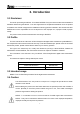

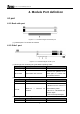
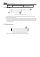
Table Of Contents

无锡人人行拍网络科技有限公司
5
4. Module Port definition
4.1 port
4.1.1 Back side port
Figure 4.1.1.1 schematic diagram of back side port
[1]: Camera port: For connect the camera.
4.1.2 Side 1 port
Figure 4.1.2.1 schematic diagram of side 1 port
[1]: Work light, For monitoring the g transmitter operating status.
Light status
Description
Operation
Flash regularly Transmitter works well NA
Other status Transmitter does not work
Connect t he system t o t he
power agai n, or c ontact with
the customer service.
[2]: Link light, for monitoring the status of connect with the receiver.
Light status Description Operation
Turn-on Connect with receiver well NA
Turn-off
Does not c onnect w ith
receiver
1. Please wait for connecting
2. M ake s ure t he r eceiver i s
connected the power.
3. B ind t he Transmitter and
receiver again
4. Connect the power again
[3]: CAM light:For monitoring the status of connect with the camera.
Light status
Description
Operation
Turn-on
Connect with camera well
NA