
Instruction manual


7
Technical Support: support@wyrestorm.com US: +1 866 677 0053 EU: +44 (0) 1793 230 343
1
2
3
4
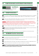
RJ45 TERMINATION AND CAT5E/6 CABLE DISTANCE, INITIAL CONNECTION AND IR/RS232 CONTROL CONNECTION
7ii. RJ45 Termination and Cat5e/6 Cable Distance
1
2
3
4
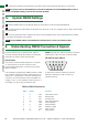
Cat5e Wiring Guide
The quality of termination
for every RJ45 is
essential. Poor terminations leads to intermittent
performance and longer install times.
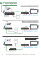
7iii. Initial Connection
Firmly connect an HDMI input (such as Blu-Ray, games console, satellite/cable, media server etc.) to a HDBaseT
transmission device (such as a WyreStorm HDBaseT transmitter, AMP-001-010 digital amplifier or Pro Plus matrix
solution.)
Connect a good quality, well terminated Cat5e/6 cable of no more than 70m/230ft in length between the UTP/
HDBaseT output of the transmission device to the HDBT IN of the RX-70-PP
Attention 70m/230ft is the maximum recommended transmission distance for this classification of
HDBaseT equipment and denotes perfect transmission conditions - including straight cable runs with no
electrical interference, bends, kinks, patch panels or wall outlets. If any of the above are a factor in your
installation, transmission range may be affected – take care to avoid where possible.
Connect the HDMI sink (LED /Plasma display / digital projector) to the HDMI OUT of the RX-70-PP receiver.
NOTE We strongly recommend using the supplied mounting brackets to secure the receiver. Any sudden movement of
devices can lead to loss of picture/sound if connections become loose or strained,
resulting in unnecessary service call backs.
If daisy-chaining receivers, repeat process for all RX-70-PP units installed from your transmission devices.
For two way control of connected sources and displays from either location, connect IR transmitters to the IR TX
ports of the HDBaseT Transmitter devices and RX-70-PP.
Insert IR receivers into IR RX ports of the HDBaseT Receiver devices and matrix.
If using an RS232-based control system, insert cables into the RS232 ports of devices to enable RS232 control.
Ensure IR TX transmitters are firmly attached over IR sensors of devices to be controlled.
NOTE If unsure of positioning, IR sensors can be located on devices by shining a flashlight onto the facia
of the device - the IR sensor should be identifiable as a small round sensor behind the panel. Consult your
device manufacturer handbook if difficulties are experienced.
7iv. IR/RS232 Control Connection
Cat5e/6 Cable Performance Guide
RX-70-PP
0ft 328ft32ft 65ft 98ft 131ft 164ft 197ft 230ft 262ft 295ft
0m 100m10m 20m 30m 40m 50m 60m 70m 80m 90m