
Instruction manual


8
Technical Support: support@wyrestorm.com US: +1 866 677 0053 EU: +44 (0) 1793 230 343
UPDATE RS232 SETTINGS AND UNDERSTANDING RS232 CONNECTION & SIGNALS
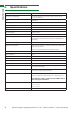
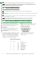
DB-9 DB-25 Function
1 8 DCD Data Carrier Detect
2 3 RxD Receive Data
3 2 TxD Transmit Data
4 20 DTR Data Terminal Ready
5 7 GND Ground (Signal)
6 6 DSR Data Set Ready
7 4 RTS Request to Send
8 5 CTS Clear to Send
9 22 RI Ring Indicator
DB-9 to DB-25 Conversion
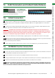
7v. Update RS232 Settings
8. Understanding RS232 Connection & Signals
RS-232C, EIA RS-232, or simply RS-232, refers to
the same standard defined by the Electronic Industries
Association in 1969 for serial communication.
DTE and DCE
DTE stands for Data Terminal Equipment. A computer
or control system is DTE and connects to Data
Communication Equipment, or DCE such as an Amp,
Matrix or Modem.
DTE equipment typically feature a Male Connector, while
DCE contains a Female Connector, although that is not
always true - a simple way to confirm is to measure Pin
3 and Pin 5 of a DB-9 Connector with a Volt Meter. If a
voltage of -3V to -15V is achieved, the device is DTE. If
the voltage is on Pin 2, then the device is DCE.
NOTE: The result for a DB-25 Connector is reversed
(Please refer to DB-9 to DB-25 conversion table)
1 2 3 4 5
6 7 8 9
RS-232 Pin outs (DB-9)
A male DB-9 connector viewed from the front.
Reverse or back view of male connector for
Female Connector.
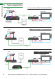
Ensure IR RX receivers are positioned in clear line of sight to the remote handset used to control them.
NOTE For serial control via the RS232 port on the RX-70-PP please ensure the MODE switch is set to
Normal. The Update setting is reserved for firmware updates.
Move the MODE switch to the Update setting for the receiver to enter Firmware Update Mode
Connect a Serial-to-USB cable from the RS232 port of the RX-70-PP to a computer and run VS010 RX Firmware
Update batch file.
Once the update has been completed, be sure to return the MODE switch to the Normal position for RS232
control signal transmission to be passed.
NOTE Connect RS232 cables to the RS232 port of the Receiver to form one extension cable.
5
1
2
3