Wyrestorm HDBaseTTM Class D Digital Audio Amplifier / Receiver / Repeater Part Number AMP-001-010 Instruction Manual Thank you for choosing this WyreStorm product. Please read these instructions carefully before installing to avoid complications later. Technical Support: support@wyrestorm.
CONTENTS AND INTRODUCTION Contents 13 EDID Management i. About EDID ii. Before EDID adjustment iii. EDID Pre-sets 1 Introduction 2 Features 14 Troubleshooting 3 Safety Precautions 4 Package Contents 15 FAQ’s 5 Specifications 6 Panel Descriptions i. Front ii. Rear 7 Connection and Operation i. Cabling Guide ii. RJ45 Termination iii. Initial Connection iv. IR/RS232 Control Connection v.
USB to 5V Cable Part Number CAB-USB-5V • Conforms to IEEE-568B standards Employing a switching topology, the low voltage, energy efficient digital Class D amplification delivers power to the • Each HDMI port also supports DVI signals. speaker load exclusively with very little power wasted in • Each Output port can be fed to multiple displays operation. This increase in efficiency has the main (cascaded).
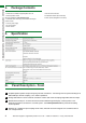
PACKAGE CONTENTS, SPECIFICATIONS AND PANEL DESCRIPTIONS 4. Package Contents 1 x AMP-001-010 HDBaseT Digital Amplifier main unit 1 x Remote control handset 1 x Printed product manual 2 x Installation brackets (recommended) (also downloadable at www.wyrestorm.com) 1x USB - Serial Cable (pheonix connector) 1 x USB flash drive containing control software and digital product manual 1 x 18v DC power supply 1 x IR TX transmitter 1 x IR RX receiver 5. Specification 6i.
Pre-out Stereo Audio Output (DAC > Digital Analog Converter) for direct connection to external amplifier/AVR via stereo RCA cables (Note: when external power amplification is used, speakers and Subwoofer should be connected directly to the AVR). 6 IR RX control receiver port - for receiving infrared control signals and sending back to centralized source & AMP function control. 7 IR TX control transmitter port - For transmitting infrared control signals from central location to control TV function.
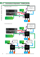
CONNECTION & OPERATION - CABLING GUIDE 7i. Connection & Operation - Cabling Guide Multiple Inputs via MX0808-PP with additional Local audio input & ARC Local Audio Source HDMI/ ARC Full 1080p HD Audio Video from centralized source via Cat5e/6 IR Transmitter IR Control 70m/230ft Single Cat5e/6 RS232 RS232 AMP-001-010 1. AV Source> 2. ARC> 3.
HDMI/ ARC Local Audio Source AV Source IR Receiver IR Control HDMI TX-IR-70 CONNECTION & OPERATION - CABLING GUIDE Full 1080p HD Audio Video from centralized source via Cat5e/6 AMP-001-010 1. AV Source> 70m/230ft Single Cat5e/6 2. ARC> 3. Local Input> RS232 IR Transmitter Extended Multiple Inputs Local Audio Source AV Source IR Control HDMI TX-IR-70 70m/230ft Single Cat5e/6 RS232 RS232 HDMI/ ARC Full 1080p HD Audio Video from centralized source via Cat5e/6 AMP-001-010 1. AV Source> 2.
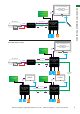
AMP-001-010 Centralized with Wyrestorm Matrix with managed Lip Sync CONNECTION & OPERATION - CABLING GUIDE Speaker Cable to In-Ceiling Speakers AMP-001-010 18V Cat5e/6 HDMI 70m Single Cat5e/6 Full 1080p HD Audio Video from centralized source via Cat5e/6 RX-IR-70 AMP-001-010 In-line adjacent with In-Ceiling speakers Speaker Cable to In-Ceiling Speakers TX-IR-70 70m Single Cat5e/6 18V AMP-001-010 HDMI 70m Single Cat5e/6 Full 1080p HD Audio Video from centralized source via Cat5e/6 RX-IR-70 AM
RJ45 Termination Cat5e Wiring Guide The quality of termination for every RJ45 is essential. Poor terminations leads to intermittent performance and longer install times an HDBaseT repeater to extend the transmission as well as a Receiver, with the inclusion of up to 7 units connected along a single cable run. As such, an RX-1UTP-IR-70 receiver is only required to extend the final leg of the distribution a further 70m/230ft, or if HDMI output and IR/RS232 control only is required.
OPTIONAL DEVICE CONNECTION, INTERFACE DEVICE, BASIC & REMOTE CONTROL OPERATION 7v. Optional Device Connection 1 For connection of local line level audio sources (such as MP3 player, multiroom audio system, laptop/ desktop, smartphone/tablet, mixer, microphone etc) connect a 3.5mm mini jack from the audio source to the L/R port of the AMP-001-010 1 Turn on the AMP-001-010 using the POWER switch on the front panel – LED will indicate power status.
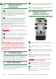
Onscreen User Interface ONSCREEMN USER INTERFACE 10. 1 3 4 2 10 6 5 7 8 9 Attention: Amps must be individually connected and have their addresses assigned first, before installation.
AMP-001-010 APPLICATION SCENARIOS - BASIC AND EXTENDED CENTRALIZED SOURCE 11i. Application Scenarios and Installation Benefits - Basic Centralized Source AMP as Cat5e Extender/Receiver No compromise in extender performance – 1080p 36Bit The most progressive extender solution currently available Overcome your competitors with a better solution IR rx RX ir Huge up-sale opportunities from conventional extender product Higher Value, Add Speakers, Subs, Cables to increase profit 11ii.
Basic Matrix BASIC MATRIX AND EXTENDED MATRIX 11iii. 4x4, 6x6, 8x4 or 8x8 Pro Plus Matrix Solution Add 4, 6 or 8 centralized sources while maintaining full AMP integration as a Amplifier, Receiver, Transmitter and repeater for even greater flexibility for residential and commercial applications. HDBaseT Output on Each Matrix Output Same cable transmission as a basic single source system, with the same advantages of HDBaseT technology… multiplied.
AMP-001-010 AS DISPLAY RECEIVER AND AMP AS IN-LINE SOLUTION 11v. AMP-001-010 as Display Receiver AMP as a Receiving Device Simple installation of the AMP between a transmission transmission device and the display, with local, direct speaker connection. Choice of Transmission Device Single source transmitter or multi-source matrix - the choice is yours - the installation procedure is identical.
Central Configuration AMP Located Centrally* AMP can be positioned at a central point, such as a rack, and connected to the transmission device via a short patch lead. Delay Set BypassD elay 1 Status Delay 2 MUTE Managed Lip Sync Set Via PC As mixing analog audio and digital video can often cause sync issues, the AMP contains settings and software to overcome such difficulties. *ARC not supported in this instance Rx-70-ir-pp IR rx RX ir (arc notsupported) supported) hdmihdmi (arc not 0.
UNDERSTANDING RS232 CONNECTION & SIGNALS DTE Pin Assignment (DB-9) 1 2 3 4 5 6 7 8 9 DCD RxD TxD DTR GND DSR RTS CTS RI Data Carrier Detect Receive Data Transmit Data Data Terminal Ready Ground (Signal) Data Set Ready Request to Send Clear to Send Ring Indicator DCE Pin Assignment (DB-9) 1 2 3 4 5 6 7 8 9 DCD TxD RxD DSR GND DTR CTS RTS RI Data Carrier Detect Transmit Data Receive Data Data Set Ready Ground (Signal) Data Terminal Ready Clear to Send Request to Send Ring Indi
Zonal IR for Cascading Multiple Independently Controlled AMP units ZONAL IR AND GLOBAL IR CONTROL 12ii. Individual IR Receivers for Independent Operation Independent Zonal IR control is possible for individual, daisy-chained AMPs using separate IR receivers at display points. Full Control of Each and Every Amp Individual IR Receivers enables commands to be sent to AMPs separately.
HYBRID IR AND RS232 ADDRESSING 12iv. Hybrid IR for combination of Zonal and Global IR control of multiple AMP units Final IR Receiver has overall control of all AMPs albeit with variations Each AMP has local IR Control Cat5e/6 cat5e/6 Cat5e/6 cat5e/6 global ir. all amps controlled together from display at the end of the chain HDBT out out hdbt global ir.
ROUTABLE RS232 WITH WYRESTORM POH ENABLED HDBASET MATRICES 12vi. Routable RS232 with Wyrestorm POH enabled HDBaseT Matrices - MX-PP-POH MX-PP-POH Range offers More for AMP Integration The MX-PP-POH range are customizable Pro Plus matrices in 8x8 and 16x16 that offer a choice of 8 different analog and digital transmission cards, each converting to 70m/230ft HDBaseT Outputs.
RESIDENTIAL RS232 HDBASET ADDRESSING EXAMPLE More Control PoH-enabled matrices also feature routable RS232 to allow each display zone to be independently controlled, which means up to 7 individually addressed AMPs can be connected to each output of the matrix, with serial control commands sent centrally through the RS232 port of the matrix to any specific Amp/group of Amps within the 8 or 16 separate control zones, depending on the matrix model.
Example System Topology showing multiple, differently addressed Amps Technical Support: support@wyrestorm.com US: +1 866 677 0053 EU: +44 (0) 1793 230 343 RESIDENTIAL RS232 HDBASET ADDRESSING EXAMPLE 12viii.
COMMERCIAL RS232 HDBASET ADDRESSING EXAMPLE AND EDID 12ix. Commercial RS232 HDBaseT Addressing example Mute Command -> mut 03 3 Volume Down -> vol 01 01 [01 is command for down] 5 3 3 COMMAND Input Format ->command[space]add[space]variable 3 4 key: Amp address M 13i. matrix 1 1 1 1 EDID Management About EDID 8 2 8 M 7 6 as communication between display and amplifier is the most important in the system.
EDID Presets EDID DIP Switch settings 1 (Down):ON 0 (Up): OFF X: Either position - does not effect function 1 2 3 4 ON DIP 1 2 3 4 ON DIP EDID subject to PC: settings via DIP switch deactivated adjustment by PC (Default Factory Setting) EDID set to copy HDMI OUTPUT EDID 1 2 3 4 EDID set to copy HDBaseT OUTPUT EDID 1 2 3 4 EDID set to fix 1080p 2ch stereo 3D 1 2 3 4 EDID set to fix 1080p 2ch stereo 2D 1 2 3 4 EDID subject to DIP switch: settings via PC deactivated adjustment by unit DIP switch
TROUBLESHOOTING 14. Troubleshooting Generally, the majority of HD distribution installation issues are either caused by minor connection errors, communication problems between devices, or when the transmission of high signal bandwidth is attempted using insufficient cable.
9) Electrical interference – HDBaseT is less susceptible to interference compared to regular transmissions but the location of cables and devices should be considered - could any form of interference be generated? If so, attempt to remove the source of electrical interference or move the cable run to decrease the effects of the interference.
FAQ’S a maximum of 1080p, 50Hz. Higher resolutions available for graphics-based systems require higher bandwidth that may affect transmission of signals as well asincompatibility with devices. IR 1) Check emitters at the IR TX transmitter end and receivers at the IR RX receiver end – are they connected to the correct ports on the matrix and display receiver.
How do I control the sources? All of our HDMI distribution products support IR passthrough from point-to-point extender sets to AMP and HDBaseT matrices. Most of the range now supports wideband IR meaning it is compatible with any IR device available on the market. Our PP and HDBaseT matrix range (Cat 5e/Cat6) has IR pass-through from each of the outputs and has discrete IR outputs at the switch end, meaning you can have multiple identical sources yet the IR would be routed only to the applicable source.
MAIL-IN-SERVICE, WARRANTY AND WARRANTY LIMITS AND EXCLUSIONS 17. Provided Service 1. Damage requiring service: This unit should be serviced by a qualified service personnel if: • The DC power supply or AC adaptor has been damaged. • Objects or liquid have gotten into the unit. • The unit has been exposed to rain. • The unit does not operate normally or exhibits a marked change in performance. • The unit has been dropped or the cabinet damaged. 2.
INSTALLATION NOTES content. The items listed here are not exclusive, but are for illustration only. Parts and service not covered by this limited warranty are not the responsibility of the warrantor and should be considered the responsibility of the individual. 20. Installation Notes AMP-001-010 Installation Reference Log Technical Support: support@wyrestorm.
INSTALLATION NOTES 30 Technical Support: support@wyrestorm.
INSTALLATION NOTES Technical Support: support@wyrestorm.
www.wyrestorm.com www.wyrestorm.com www.wyrestorm.