Part Number MX-0606-PP 6 Input 6 Output single cable matrix with 2 way IR control Part Number MX-0808-PP 8 Input 8 Output single cable matrix with 2 way IR control Wyrestorm Pro Plus HDBaseT Matrix Solutions Instruction Manual Thank you for choosing this WyreStorm product. Please read these instructions carefully before installing to avoid complications later.
CONTENTS AND INTRODUCTION Contents 1 Introduction 2 Features 3 Safety Precautions 4 Package Contents 5 Specifications 6 Front Panel Description 7 Rear Panel Description 8 Typical Application 9 Connection 10 Basic Operation i. Front Panel Control ii. Remote Control at Matrix end (Local IR) and Battery Replacement iii. Matrix System Code Switch – control two matrices with one handset iv. Remote Control at the Display End (Remote IR) v. Handset Output/Source select Key Code vi.
2. Features • Each output able to show any connected source simultaneously regardless of whether the input carries HDCP encryption. • Refined for Custom Install and Home Theatre Installations. • Quick and easy installation – set up in seconds straight out of the box. • Reads and copies EDID from connected devices with additional EDID configuration through customisable DIP switch settings if • Simplified ports - Input: HDMI – Output: Simultaneous HDMI and necessary.
HDMI to HDMI coupleHDMI r RP-to HDMI coupler RPMaximum Single Link Range 1080p Deep Colour Maximum Single LinMaxi k Rangemum1080p SinglDeepe LiColnkourRange 1080pHD-HD. Deep Colour HD-HD. 4.4. Package PackageContents Contents PACKAGE CONTENTS AND SPECIFICATIONS PACKAGE CONTENTS AND SPECIFICATIONS PACKAGE CONTENTS AND SPECIFICATIONS PACKAGE PACKAGE CONTENTS CONTENTS AND AND SPECIFICATIONS SPECIFICATIONS al copy al copy com com ) ) / /ssng ong onds, llnds, mll RXmivers RXivers ay. ay. 70m) 70m) 70 70 4.
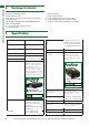
1 Front Panel 4 LED Input/Output Select Screen 2 3 Output Select Buttons (Left/Right) 5 IR Receive Window Enter Selection Buttons 6 Input Select Buttons (UP/DOWN) FRONT PANEL AND REAR PANEL 6.
TYPICAL APPLICATION, TYPICAL APPLICATION CONNECTION 8. 8.
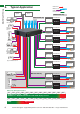
HDMI Source HDMI Source HDMI Source KEY KEY KEY 0101 01 IRTX Emitter IRTX Emitter IRTX Emitter IRRX Receiver IRRX Receiver IRRX Receiver 0303 optional optional optional HDMI HDMIHDMI 03 UTP Cat5e/6/7 UTP Cat5e/6/7 UTP Cat5e/6/7 IR IR RXRX jack plugged intointo IR RX jack plugged into jack plugged IR IR RXRX port of matrix with IR RX port of matrix withIR IR port of matrix with TXTX emitter securely IR TXplaced emitter placed securely emitter placed securely 0202 02 receiver placed in clear receive
TYPICAL APPLICATION, BASIC OPERATION using Cat5e as standard, we suggest using Cat6 as the preferred cable due to its improved transmission capabilities. If using a Duplicate display mirrored to the HDBT Output, connect the display via the HDMI OUT port. ATTENTION We strongly recommend using the supplied mounting brackets to secure the MATRIX and the accompanying TRANSMITTER & DISPLAY RECEIVER baluns.
OUTPUT OUTPUT CHANNEL CHANNEL 6 6 7 7 8 8 System Code SwitchCode Switch System INPUT SELECT INPUT SELECT 1 1 The default system setting is 0x00 to control one matrix, but default ison0x00 to control one matrix, AsThe such, thesystem function of the handset buttons and but pressing the SYSTEM CODEsetting button the handset THREE OUTPUT INPUT SELECT pressing the SYSTEM CODE button on the handset THREE TIMES rapidly activates alternative Matrix SYSTEMthe CODE operation differsthedepending onCHANNE
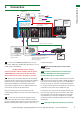
OL so when an OUTPUT selects a certain INPUT, the CALL-BACK IR signal of that RJ45 port selects the relevant IR TX port to OUTPUT the control signal. Display Reciever IR Path IR Receiver 3 1 2 3 4 2 4 3 4 4 1 2 3 HDBT OUT 1 HDBT OUT 2 HDBT OUT 3 HDBT OUT 4 4 HDBT OUT 5 HDBT OUT 6 HDBT OUT 7 HDBT OUT 8 signal to be combined and communicated for that input to be controlled remotely.
-RX2) with signal to HDMI and carried As with thethe IR IR TX, thethe IRconverted RX are allocated to their Output2-RX2) with IRports signal converted to HDMI Insert 3.5mm jacks of ports IRcable. RX (Output1-RX1, receivers into RX ports, along the single Cat5e/6/7 respective UTP OUTPUT Output2 and carried along single Cat5e/6/7 cable. making sure the the receivers themselves are placed in -RX2) with the IR signal converted to HDMI and carried Insert 3.
ADVANCED REMOTE CONTROL ADVANCEDADVANCED REMOTE CONTROL REMOTE CONTROL 11. Advanced Remote Control 11.
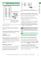
15 01 16 MX-0606-PP 9 17 MX0606-PP MX0606-PP 03 04 04 06 06 07 02 03 02 1 05 05 3 2 MX-0808-PP 10 11 10 10 11 11 10 10 11 11 10 1112 12 07 08 08 4 Receive Message WindowWindow 01 Receive Message 5 01 02 Matrix 02 Status Matrix Status 10 11 10 11 10 11 12 03 Message 03 Message 6 Clear Clear 7 8 06 Com State -State Shows if the matrix connected 06 Connect Com Connect - Shows if the is matrix is connected 04 1Send Message Window 04 Send Message or disconnected to the Com Port and communi
8 button again to Connect and power-cyle the matrix (turn off and on). ADVANCED OPERATION A large yellow number denotes each OUTPUT section with INPUTS chosen by either clicking the left/right arrow buttons to scroll through inputs numerically or by pressing the input numbers below. The INPUT/OUTPUT switch allows output port selection (display) and Input port select (source) buttons for specific combinations of displays and sources within the matrix. combinations displays and sources the matrix.
will instruct matrix to attempt to aid transmission of the HDMI signal. This setting is locked by default. 14 14 2 4 UTP LONG CABLE MODE – As with HDMI Long Cable Mode, if signal transmission quality is affected by a Cat5e/6/7 cable run reaching the maximum distance capacity (70m / 230ft using RX-1UTP-IR-70), switching Long Cable Mode to ON will instruct the matrix to attempt to improve transmission over the UTP in an effort to improve signal quality.
1- Press to changes to the to save savethe the changes tosystem. the system. to save the changes to the system. 5- Hit 5- Hit 5- Hit to close the IR Code Setting window and the device will enter NORMAL MODE to close the IR Code Setting window and the device will enter to close the IR Code Setting window and the device will NORMAL MODE enter NORMAL MODE A A B B A 01 01 ADVANCED OPERATION ADVANCED OPERATION to instruct COM CTL to read the IR code from the control system.
x via ird x via e eird ed ed if if ems ms e ode ode des. des. ed if ms ed if ms ode des. ode des. ..
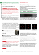
3 Once completed, the EDID appears here. ADVANCED OPERATION NETCTL - LAN Control The matrix can also be controlled via LAN over a network/ web browser using the supplied Wyrestorm NET CTL software or LAN protocols from third party companies, such as Control 4.
ADVANCED OPERATION to attach the IP address to the system and the IP address will change to a default factory serial number MX0606-PP or MX0606_HE1 / MX0808-PP or MX0808_HE1 Device Name ADVANCED OPERATION Should you wish to change the name of your matrix from the factory default, just right click on the serial number and select ‘rename’ from the dropdown menu. Input the new name and press OK. In some systems these settings can be accessed through the included Netfinder.exe application.
The layout of NET CTL includes an upper section to allocate input sources to output with the selection displayed on the left hand side. Operation is the same as COM CTL – Inputs buttons 1-4 can be clicked to be selected per Output port. ADVANCED OPERATION Press the button to update your chosen matrix settings into the left hand display and your selection to take effect.
For example: If OUTPUT 3 is selected for INPUT 1, the EDID ADVANCED ADVANCED OPERATION OPERATION ADVANCED ADVANCED OPERATION ADVANCED OPERATION OPERATION ADVANCED OPERATION ADVANCED OPERATION To reset EDID for all ports, simply set the DIP switch to for OUTPUT 3 will be copied to INPUT 1 – this is achieved by the above position when the matrix is powered OFF. On the system setting HDMI OUTPUT as a higher priority than UTP powering ON, all ports3will revert to above factory ON OUTPUT.
TROUBLESHOOTING 12. Troubleshooting Generally, the majority of HD distribution installation issues are either caused by minor connection errors, communication problems between devices, or when the transmission of high signal bandwidth is attempted using insufficient cable.
13) Picture snow/HD ‘noise’ – represents a poorly established signal that may be caused by poor quality terminations or excessive cable lengths. Try swapping the display adaptors from a location you know is functioning properly or swapping the outputs of the matrix switch used.
a signal being sent. Replace batteries if flashing is not seen on the digital camera screen. TROUBLESHOOTING AND FAQS 4) IR dropout issues can be due to exterior influences emitting infrared radiation that can interrupt IR signals. Ensure emitters and receivers are away from the following causes of IR interference. • Direct sunlight • Halogen lighting • Plasma screens 5) UTP Termination Issues - swap cables over at both transmitter and receiver ends to see if control is established.
Using our conventional pro (TMDS) transmission method the Video & Audio is sent along cable #2, IR and HDCP data is sent along cable #1. Using our HDBaseT technology it’s possible to send Audio (up to DTS Master), Video (up to 4k), Ethernet (10/100), and control (RS232 & 2-way IR) down a single Cat 5e cable. Are Wyrestorm products compatible with HDMI 1.4? HDMI 1.4 refers to a list of ‘features’ that a device is capable of supporting, including Ethernet channel, return audio channel, 3D etc.
MAIL-IN-SERVICE AND WARRANTY 16. Mail-in-service When shipping the unit, carefully pack and send it prepaid, with adequate insurance and preferably in the original packaging. Please include a document or letter detailing the reason for return and include a daytime telephone number and/or email address where you can be contacted.
INPUT REFERENCE LOG INPUT REFERENCE LOGS 19. Reference Logs Wyrestorm Matrix INPUT installation reference log INPUT Input number on Matrix Source Location Source Details Source resolution & audio settings Cable Number 1 2 3 4 5 6 7 8 27 Technical Support: support@wyrestorm.
OUTPUT REFERENCE LOG OUTPUT REFERENCE LOGS Wyrestorm Matrix OUPUT installation reference log OUTPUT Output number on Matrix Output Location Display Details Display Resolution & Audio Settings Cable Number 1 2 3 4 5 6 7 8 28 Technical Support: support@wyrestorm.com US: +866 677 0053 EU: +44 (0) 1793 230 343 Technical Support: support@wyrestorm.
NOTES Technical Support: support@wyrestorm.
NOTES 30 Technical Support: support@wyrestorm.
NOTES Technical Support: support@wyrestorm.
www.wyrestorm.com WyreStorm Offices US Office: 6991 Appling Farms Parkway, Suite 104, Memphis, TN 38133 Tel: + 901 384 3575 Fax: + 901 384 3574 Unit 22, Ergo Business Park, Swindon, Wiltshire, SN3 3JW UK Tel: +44 (0) 1793 230 343 Fax: +44 (0) 1793 230 583 WyreStorm Technical Support US: +86 6677 0053 UK:- +44 (0) 1793 238 338 Email: support@wyrestorm.com We reserve the right to change specification or product dimensions at any time.