
Instruction manual


5
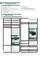
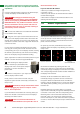
6. Front Panel
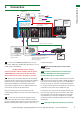
7. Rear Panel
FRONT PANEL AND REAR PANEL
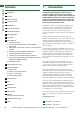
RS232 and LAN ports are for matrix control. Ensure crossover UTP cable is used to connect the LAN directly to a
computer or server, and a direct/straight through connection is used to connect via a router/switch. Connection
will fail if the incorrect cable is used.
1
1
4
2
2
5
7
3
3
6
8
4
9
12
5
10
13
15
6
11
14
16
EDIDIR EXT
IR RXH DMI OUT HDBT OUTHDMI IN
IR RXH DMI OUT HDBT OUTHDMI IN
IR RXH DMI OUT HDBT OUTHDMI IN
IR RXH DMI OUT HDBT OUTHDMI IN
IR RXH DMI OUT HDBT OUTHDMI IN
IR RXH DMI OUT HDBT OUTHDMI IN
IR TX
123456
RS485 RS232LAN
1 2 3GROUP4 5 6
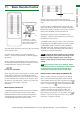
RJ45 + RS285 DEFINITION
RJ45 PIN 1 2 7 8
DESCRIPTION TX+ TX- RX+ RX-
DEFAULT
1
1
0
ON
OFF
23 4
5
7
6
8
9
12
1
4
10
13
15
2
11
14
16
3
EDIDIR EXT
IR RX HDMI OUT HDBT OUTHDMI IN
IR RX HDMI OUT HDBT OUTHDMI IN
IR RX HDMI OUT HDBT OUTHDMI IN
IR RX HDMI OUT HDBT OUTHDMI IN
IR RX HDMI OUT HDBT OUTHDMI IN
IR RX HDMI OUT HDBT OUTHDMI IN
IR TX
123456
RS485 RS232LAN
IR RX HDMI OUT HDBT OUTHDMI IN
IR RX HDMI OUT HDBT OUTHDMI IN
1 2 3GROUP4 5 6
RJ45 + RS285 DEFINITION
RJ45 PIN 1 2 7 8
DESCRIPTION TX+ TX- RX+ RX-
DEFAULT
1
1
0
ON
OFF
23 4
5
7
6
8
9
12
1
4
10
13
15
2
11
14
16
3
LED Input/Output Select Screen
HDBT Output ports (RJ45 Cat5e/6/7)
IR Receiver port (IR RX)
Output Select Buttons (Left/Right)
RS485 port
RS232
IR Receive Window
Duplicate HDMI Output ports (mirrors HDBT Outputs)
AC 100 – 240V power input
Power switch
Enter Selection Buttons
LAN port
IR Extension port (IR EXT)
EDID switch default diagram
Input Select Buttons (UP/DOWN)
HDMI Input ports
Fuse (lift cover to replace)
Input/Output port grouping indicator
Rack Brackets
RJ45 to RS485 denition indicator
EDID DIP Switch (for manual EDID setting)
IR TX Receiver ports (corresponds to input ports)
Technical Support: support@wyrestorm.com US: +866 677 0053 EU: +44 (0) 1793 230 343
ENTER
1
2
3
3
44 66
5
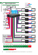
Part Number MX-0606-PP
Part Number MX-0808-PP